Download
1 / 7
70 likes | 74 Views
In our country power is distributed to various areas through the grid. Different generating stations generate electricity of 11kv and transfers power to the grid. Then the power is transferred to the substations through the transformers. This power is distributed to the consumers through various distribution systems to improve the efficiency. The efficiency of the distribution system is less due to more losses and natural calamities will affect the distribution system. It may cause the failure of the power supply to the consumers and it will affect the entire power distribution system or we need to re install the entire distribution lines. These all are the disadvantages of distribution system. Under peak loaded condition bulk amount of power is needed to meet the load demand. And under heavy loaded condition the supply to the consumers will shut down for some time to meet the load demand. Therefore, the entire efficiency of the distribution system is less. However, this paper is discussing about losses allocation at each node in radial distribution system and improving efficiency of radial distribution system. So, we need to improve the efficiency of the distribution system. By using different techniques, we can improve the efficiency of the radial distribution system. R. Vijaya Krishna | K. Sarath Kumar | M. Jeevana Rao "Minimization of Power Losses In Radial Distribution System- A Review" Published in International Journal of Trend in Scientific Research and Development (ijtsrd), ISSN: 2456-6470, Volume-2 | Issue-1 , December 2017, URL: https://www.ijtsrd.com/papers/ijtsrd5834.pdf Paper URL: http://www.ijtsrd.com/engineering/electrical-engineering/5834/minimization-of-power-losses-in-radial-distribution-system--a-review/r-vijaya-krishna<br>

E N D
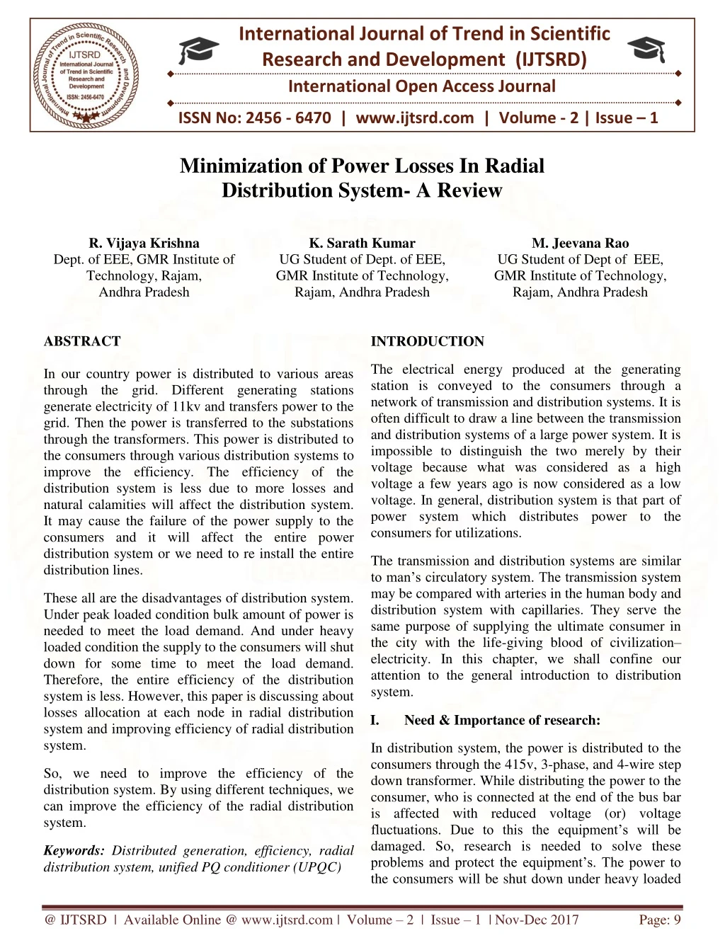
International Journal of Trend in Scientific Research and Development (IJTSRD) International Open Access Journal ISSN No: 2456 - 6470 | www.ijtsrd.com | Volume - 2 | Issue – 1 Minimization of Power Losses In Radial Distribution System- A Review R. Vijaya Krishna Dept. of EEE, GMR Institute of Technology, Rajam, Andhra Pradesh K. Sarath Kumar UG Student of Dept. of EEE, GMR Institute of Technology, Rajam, Andhra Pradesh M. Jeevana Rao UG Student of Dept of EEE, GMR Institute of Technology, Rajam, Andhra Pradesh ABSTRACT In our country power is distributed to various areas through the grid. Different generating stations generate electricity of 11kv and transfers power to the grid. Then the power is transferred to the substations through the transformers. This power is distributed to the consumers through various distribution systems to improve the efficiency. The efficiency of the distribution system is less due to more losses and natural calamities will affect the distribution system. It may cause the failure of the power supply to the consumers and it will affect the entire power distribution system or we need to re install the entire distribution lines. INTRODUCTION The electrical energy produced at the generating station is conveyed to the consumers through a network of transmission and distribution systems. It is often difficult to draw a line between the transmission and distribution systems of a large power system. It is impossible to distinguish the two merely by their voltage because what was considered as a high voltage a few years ago is now considered as a low voltage. In general, distribution system is that part of power system which distributes power to the consumers for utilizations. The transmission and distribution systems are similar to man’s circulatory system. The transmission system may be compared with arteries in the human body and distribution system with capillaries. They serve the same purpose of supplying the ultimate consumer in the city with the life-giving blood of civilization– electricity. In this chapter, we shall confine our attention to the general introduction to distribution system. These all are the disadvantages of distribution system. Under peak loaded condition bulk amount of power is needed to meet the load demand. And under heavy loaded condition the supply to the consumers will shut down for some time to meet the load demand. Therefore, the entire efficiency of the distribution system is less. However, this paper is discussing about losses allocation at each node in radial distribution system and improving efficiency of radial distribution system. I. Need & Importance of research: In distribution system, the power is distributed to the consumers through the 415v, 3-phase, and 4-wire step down transformer. While distributing the power to the consumer, who is connected at the end of the bus bar is affected with reduced voltage (or) voltage fluctuations. Due to this the equipment’s will be damaged. So, research is needed to solve these problems and protect the equipment’s. The power to the consumers will be shut down under heavy loaded So, we need to improve the efficiency of the distribution system. By using different techniques, we can improve the efficiency of the radial distribution system. Keywords: Distributed generation, efficiency, radial distribution system, unified PQ conditioner (UPQC) @ IJTSRD | Available Online @ www.ijtsrd.com | Volume – 2 | Issue – 1 | Nov-Dec 2017 Page: 9
International Journal of Trend in Scientific Research and Development (IJTSRD) ISSN: 2456-6470 conditions in order to provide the supply for bulk consumers. Due to this reason the continuity of supply to the consumers will be affected. In this distribution system power losses are more. Hence the efficiency of the radial distribution system is less. The main cause of reducing efficiency in electrical system is nothing but improper usage of power by the consumers. Because of this reason the maximum load or demand is reduced but maximum power generation is constant. If maximum power generation is beyond the maximum demand. We can attain maximum efficiency when maximum demand is nearly equal to maximum power generation. a loop. In these entire loop distribution systems plays a major role to feed the consumers. Generally, we are using radial distribution system while distributing the power to consumers as shown in fig-1. Fig-1 Distribution System While distributing power to the load, the distribution system has some disadvantages. They are: 1)Power loss due to Line losses 2)Low voltage at the consumer side due to voltage drop in distribution system. 3)So, efficiency of this system is low. 4)Continuity of supply is less. II.Statement of problem: The main problem in radial distribution system is Less Efficiency. The Efficiency of radial distribution system is less. Due to less efficiency the power losses will be more. IV.METHODS EFFECIENCY: TO IMPROVE THE So, reduction of power losses in radial distribution system plays a crucial role for utilization of electrical energy In order to improve the efficiency of this radial distribution system. algorithms/techniques are provided in order to improve the efficiency of the radial distribution system. Some of the a)Objectives: To improve the efficiency of the radial distribution system. A) By Placing Distribution Generation (DG) In The Distribution System. 1) To reduce the voltage fluctuations towards the consumer terminals. B) Conditioner In the Distribution System Implementing Unified Power Quality 2) To reduce the overall cost per unit paying by the consumers. A) By Placing Distribution Generation (DG) In the Distribution System [2] 3) To Increase the reliability of supply. b)Hypotheses: In our world power is distributed from generating station to load through distribution system. In distribution system efficiency plays a major role while distributing power to load. All these things will depend on losses minimization. Research on losses minimization to improve the efficiency of the distribution will have the future scope. So, the future for the research on the distribution system is more. So, improving efficiency of the distribution system had more future scope on research. Fig-2 Placement of DG in Radial Distribution System We are placing DG in radial distribution system because it will improves the efficiency of the distribution system by reducing low voltages at the consumer terminals and it increases the overall cost per unit energy consumed. III.Research methods: In our world power is generated in generating stations to feed the consumer needs. Generating power and distributing that power to consumers is entirely called If generated power is less than (or) equal to received power, then losses are said to be zero. In this case, the @ IJTSRD | Available Online @ www.ijtsrd.com | Volume – 2 | Issue – 1 | Nov-Dec 2017 Page: 10
International Journal of Trend in Scientific Research and Development (IJTSRD) ISSN: 2456-6470 method allocates zero losses to the DGs connected to the node. Most of the methods LA methods as follow in below fig-3. 1)The proposed method does not allocate negative losses to the loads and DGs. 2)The distribution system is assumed to be a radial system, in which the loads and DGs have private owners. 3)Consider the circuit depicted in Fig. 2, which shows two nodes of a system. The power loss of the line connecting nodes 1 and 2 can be written as Fig-3 Loss Allocation Method As shown in fig-3, the loss is allocated to each node due to active flows is the summation of two terms: I122*R12 . P2loss 1,2= R12*(P212+Q212/v212) =k(P212+Q212) 1) A fraction of the loss allocated to the nodes that send active power to the node, and The active generated power of all DGs connected to these nodes is consumed locally by the loads connected to these nodes. Consequently, the DGs connected to these nodes should not be allocated any active loss. 2) The loss of the lines connecting the node to the nodes that sends active power to it. As a result, one can conclude that the loads located at the end of long feeders usually allocate high losses. This can be seen in Table II, as the load connected to some node is allocated to high losses. In contrast, the loads located in places near high generation points, are allocated low proportions of loss. In other words, one of the advantages of the proposed method is considering system topology in LA. The procedure to calculate losses is as follows. Step 1) Assign zero to each of the active sink nodes, as well as the node connecting the transmission and distribution systems. Step 2) Loop over all the nodes whose is not obtained yet: If of all nodes that receive active power from this node is previously calculated, then obtain for this node First, the loss assigned to the slack node is set to zero. Since node 2 is a source node, the loss assigned to this node is zero as well Step 3) if there is a node whose is not obtained yet, go back to Step 2); otherwise, stop the procedure. Now the loss assigned to nodes 1, 3, and 4 is calculated by load allocation method. V. LOSS ALLOCATION METHOD: Imagine the distribution system shown in above Fig. The following equations show how the loss allocation to the loads of this system is calculated: LA is one of the methods to know the load allocation at each node. First, the loss assigned to the slack node is set to zero. Since node 2 is a source node, the loss assigned to this node is zero. The increase in deployment of distributed generation (DG) and the shift of distribution loads from customer mode to have altered distribution systems from passive to active mode. As a result, some of the transmission networks issues have been generalized to distribution systems as well. One of these issues is loss allocation (LA), which specifies the fraction of total distribution loss that each load or DG is responsible for. Although there are many transmission LA methods in the literature, distribution LA is still a new topic and most of the distribution system operators still do not have a standard policy. Now, the loss assigned to nodes 1,3 and 4 is calculated as: L1p=Pploss0,1+Pploss2,1 L3p=Pploss2,3 L4p=Lp1+ Pploss1,4 Similarly, the losses allocated to Distribution generation(DG) are calculated follows: as @ IJTSRD | Available Online @ www.ijtsrd.com | Volume – 2 | Issue – 1 | Nov-Dec 2017 Page: 11
International Journal of Trend in Scientific Research and Development (IJTSRD) ISSN: 2456-6470 it can also reduce the harmonic pollution created by the load. The shunt inverter injects a shunt compensating current to the load in order to provide load reactive compensation and to compensate the harmonic distortion created by the load. The series inverter is used to mitigate voltage-related problems, for example, sag and swell in supply voltage, etc. Basically, it injects a series voltage to the load. These two inverters are connected back to back with a dc link and this becomes the most common form of UPQC structure after its practical implementation reported . There are various UPQC models reported, and they are categorically presented in [1], such as UPQC-P, UPQC-Q, UPQC-S, UPQC-VA , etc. In UPQC-P, the series inverter handles only active power by injecting an in-phase voltage to the load in order to mitigate the voltage sag problem. In UPQC- Q, the series inverter mitigates voltage sag/swell by providing reactive power which is done by injecting a voltage in quadrature with source voltage. Unified power quality conditioner is as shown in fig-4: LqGj = ( (Lkq) (Qgj)2 + QGj(ƩGn<GKQGn + Ʃnɛk-1 QPn,k))/(ƩGɛGkQ Gn + ƩnɛRk-1 QPn,k ) Where Q is the reactive power Total loss allocated to DG =Sum of losses allocated for both active and reactive power. B) Conditioner in the Distribution System Implementing Unified Power Quality Fig-4: Unified Power Quality Conditioner It consists of two inverters Placement of capacitor is also a method to improve efficiency of the distribution system. 1) Series inverters 2) Shunt inverters With the advantage of advanced power-electronics technologies, extensive research is going on around the globe to improve power quality (PQ). The flexible ac transmission systems (FACTS) are the outcomes of this research. These days, similar types of technologies are used in PQ improvement in distribution systems. The unified PQ conditioner (UPQC) is one of these types of advanced power- electronics devices. By using these two inverters, a UPQC can protect a customer/load from sag, swell in supply voltage. It can also reduce the harmonic pollution created by the load. Shunt Inverter: The shunt inverter injects a shunt compensating current to the load in order to provide load reactive compensation and to compensate the harmonic distortion created by the load as shown in fig-4 Series Inverter: A UPQC is similar in construction to the unified power-flow controller (UPFC), one of the versatile flexible ac transmission systems (FACTS) devices used in transmission systems. The UPFC and UPQC provide simultaneous shunt and series compensations with a series and a shunt inverter, respectively. AUPFC works in transmission systems which are supposed to be balanced and relatively distortion free. However, a UPQC is made to operate in distribution systems which are relatively unbalanced and with higher harmonic contents due to the increasing trend of power-electronic interfaces. There is a considerably large volume of literature on UPQC and a state-of-art review can be obtained in [1]. The series inverter is used to mitigate voltage-related problems, for example, sag and swell in supply voltage, etc. Basically, it injects a series voltage to the load. In UPQC, the series inverter handles active power by injecting an in-phase voltage to the load and injecting reactive power in quandrature with the supply voltage in order to mitigate the voltage sag problem. These two inverters are connected back to back with a dc link and this becomes the most common form of UPQC structure after its practical implementation. With the two inverters, a UPQC can protect a customer/load from sag, swell in supply voltage, and @ IJTSRD | Available Online @ www.ijtsrd.com | Volume – 2 | Issue – 1 | Nov-Dec 2017 Page: 12
International Journal of Trend in Scientific Research and Development (IJTSRD) ISSN: 2456-6470 1)Placing DG in parallel with radial distribution Due to these compensating currents and voltages the power loss due to sag can be avoided. 2)Implementing unified power quality conditioner These are the techniques provided in order to improve the efficiency of the Radial Distribution system. While placing DG’S in parallel with radial distribution. Firstly, power loss in the radial distribution is calculated by using losses allocation method. We are facing some difficulties while implementation of DG’s in distribution system. They are: 1)Capital investment is more for placing DG, After the loss allocation method by determining the loads on each node. The active and reactive power flowing on each line is calculated. Then DG’s are connected to the distribution system. 2)Separate control system is needed for monitoring the DG’s 3) If renewable energy sources are used for using DG, then the efficiency will vary time to time. Then some loads are allocated to DG. So, low voltages at the end of the distribution system are minimized. By using DG’s, the reliability of the distribution system is increases. We are facing some difficulties while implementation of unified power quality conditioner in distribution system. They are: However, the overall efficiency of the distribution system is improved. We can also improve the efficiency of the radial distribution system. By implementing unified power quality conditioner in distribution system. 1) There is some loss because of usage of some dc power in it. 2)These two inverters need for separate dc power. The unified PQ conditioner (UPQC) is one of these types of advanced power-electronics devices. The UPFC and UPQC provide simultaneous shunt and series compensations with a series and a shunt inverter, respectively. With the two inverters, a UPQC can protect a customer/load from sag, swell in supply voltage, and it can also reduce the harmonic pollution created by the load. The shunt inverter injects a shunt compensating current to the load in order to provide load reactive compensation and to compensate the harmonic distortion created by the load. The series inverter is used to mitigate voltage-related problems, for example, sag and swell in supply voltage, etc. Basically, it injects a series voltage to the load. These two inverters are connected back to back with a dc link and this becomes the most common form of UPQC structure after its practical implementation reported. In UPQC-P, the series inverter handles only active power by injecting an in-phase voltage to the load in order to mitigate the voltage sag problem. In UPQC-Q, the series inverter mitigates voltage sag/swell by providing reactive power which is done by injecting a voltage in quadrature with source voltage. A comparative performance assessment of these two UPQC models. The series inverter in UPQC-S can simultaneously inject real and reactive power. In UPQC-VA, a model based on the minimization of the VA rating of the UPQC is provided. This model is reported in [5], where the 3)If there is any fault occur, in this conditioner it will affect the efficiency of the distribution system. VI.Data interpretation and analysis: DG is a small sized generator connected in parallel with the distribution system. DG is expected to play an increasing role in emerging electric power systems. Studies have predicted that DG will be a significant percentage of all new generation going on line. There are several different types of resources and technologies that can be used for DG such as wind, solar, fuel cells, hydrogen and biomass. DG can result in a network operation and planning practices with economic implications. The benefits of DG are classified into two groups: technical and economics. For example, loss, voltage profile, reliability of supply, maintenance costs, and network connection reinforcement costs can be affected by the connection of DG to the distribution system. In order to improve the efficiency and reliability of the radial distribution system. There are two techniques provided in order to improve the efficiency and reliability of the radial distribution system. They are: @ IJTSRD | Available Online @ www.ijtsrd.com | Volume – 2 | Issue – 1 | Nov-Dec 2017 Page: 13
International Journal of Trend in Scientific Research and Development (IJTSRD) ISSN: 2456-6470 optimum phase angle of the injected voltage of the series inverter is determined. However, Placing DG in parallel with radial distribution system is the best method. When compared with the implementing unified power quality conditioner in radial distribution system The two implemented techniques are categorized as one and two as shown in fig-5 REFERENCES: 9 1)M. Atanasovski and R. Tale ski, “Power summation method for loss allocation in radial distribution networks with DG,” IEEE Trans. Power Syst., vol. 26, no. 4, pp. 2491–2499, Nov. 2011. 2)J. S. Savier and D. Das, “An exact method for loss allocation in radial distribution systems,” Int. J. Elect. Power Energy Syst., vol. 36, no. 1, pp. 100– 106, 2012. 3)J. S. Savier and D. Das, “Loss allocation to consumers before and after reconfiguration of radial distribution networks,” Int. J. Elect. Power Energy Syst., vol. 33, no. 3, pp. 540–549, Mar. 2011. 4)J. S. Savier and D. Das, “Energy loss allocation in radial systems: A comparison of practical algorithms,” IEEE Trans. Power Del., vol. 24, no. 1, pp. 260– 267, Jan. 80 IEEE TRANSACTIONS ON POWER DELIVERY, VOL. 29, NO. 1, FEBRUARY 2014 5)E. Carpaneto, G. Chicco, and J. S. Akilimali, “Characterization loss allocation techniques for radial systems with distributed Elect. Power Syst. Res., vol. 78, no. 8, pp. 1396– 1406, Aug. 2008. 6)P. M. Sotkiewicz and J. M. Vignolo, “Nodal pricing for distribution networks: Efficient pricing for efficiency enhancing DG,”IEEE-Trans. Power Syst., vol. 21, no. 2,pp.1013–1014,May-2006 7)E. Carpaneto, G. Chicco, and J. S. Akilimali, “Loss and loss allocation in distribution distributed generation,” IEEE Trans. Power Syst., vol. 23, no. 3, pp. 1039–1049, Aug.-2008. 8)E. Carpaneto, G. Chicco, and J. S. Akilimali, “Computational of the marginal loss allocation methods for distribution systems with distributed generation,” in Proc. IEEE (Málaga), Spain, 2006, pp. 1028–1031.v 9)E. Carpaneto, G. Chicco, and J. S. Akilimali, “Branch current decomposition method for loss allocation in radial distribution systems with 8 7 6 5 4 Series 3 3 2 Series 2 1 0 Category 1 Category 2 Series 1 Fig-5: Analyzing Techniques In Terms Of Categories The most commonly used category is implementing DG in radial distribution system is as illustrated in below fig-5. distribution 2009. Because of following reasons: 1) It reduces the voltage fluctuations towards the consumer terminals. of the 2) It reduces the overall cost per unit paying by the consumers. generation,” 3) Increases the reliability of supply. Conclusion: Placing DG in parallel with radial distribution system is the best method when compared with the implementing unified power quality conditioner in radial distribution system because, if we use the renewable energy sources as DG‘s in radial distribution system like solar energy. We can the save the conventional energy resources. It does not consume any electrical energy. So, the efficiency of the distribution system is increases. If we implement unified power quality conditioner in distribution system. It consists of shunt and series inverters. These two inverters are connected back to back with a dc link. partitioning three-phase radial systems with aspects Melecon, Benalmádena There is some loss because of usage of some dc power in it. These two inverters need separate dc power. @ IJTSRD | Available Online @ www.ijtsrd.com | Volume – 2 | Issue – 1 | Nov-Dec 2017 Page: 14
International Journal of Trend in Scientific Research and Development (IJTSRD) ISSN: 2456-6470 distributed generation,” IEEE Trans. Power Syst., vol. 21, no. 3, pp.1170–1179, Aug. 2006. 10)R. S. Daniel, R. S. Salgado, and M. R. Irving, “Transmission loss allocation through a modified Ybus,” in Proc. Inst. Elect. Eng., Gen., Transm. Distrib., Mar. 2005, vol. 152, no. 2, pp. 208–214. 11)J. S. Savier and D. Das, “Impact of network reconfiguration allocation of radial distribution systems,” IEEE Trans. Power Del., vol.22, no. 4, pp. 2473– 2480,Oct.-2007. 12)A. J.Conejo, J. M.Arroyo, N. Alguacil, andA. L.Guijarro, “Transmission loss allocation: A comparison of different practical algorithms,” IEEE Trans. Power Syst., vol. 17, no. 3, pp. 571– 576, Aug. 2 13)R. S. Al Abri, E. F. El-Saadany, and Y. M. Atwa, “Optimal placement and sizing method to improve the voltage stability margin in a distribution system using distributed generation,” IEEE Trans. Power Syst., vol. 28, no. 1, pp. 326–334, Feb. 2013. 14)S. Jazebi, S. H. Hosseinian, and B. Vahidi, “DSTATCOM allocation in distribution networks considering reconfiguration using differential evolution algorithm,” Energy Convers. Manage., vol. 52, pp. 2777–2783, 2011. on loss @ IJTSRD | Available Online @ www.ijtsrd.com | Volume – 2 | Issue – 1 | Nov-Dec 2017 Page: 15