Download
1 / 29
330 likes | 697 Views
Understanding of Harmonics in Power Distribution System . Dr. Adel. M. Sharaf Department of Electrical & Computer Engineering University of New Brunswick. Outline. Power System Harmonics? Why Harmonics are Troublesome? Nonlinear Loads Producing Harmonic Currents Harmonic Distortion?

E N D
Understanding of Harmonics in Power Distribution System Dr. Adel. M. Sharaf Department of Electrical & Computer Engineering University of New Brunswick
Outline • Power System Harmonics? • Why Harmonics are Troublesome? • Nonlinear Loads Producing Harmonic Currents • Harmonic Distortion? • Negative Effects of Sustained Harmonics • Mitigation of the Effects of Harmonics • Evaluation of AC Power System Harmonics? • Conclusions • References EE 6633 Seminar 1
What are Power System Harmonics? • Harmonic: a mathematical definition, generally used when talking about Integral orders of Fundamental frequencies • Power system harmonics: currents or voltages with frequencies that are integer multiples (h=0,1,2,…N) of the fundamental power frequency [1] • 1st harmonic: 60Hz • 2nd harmonic: 120Hz • 3rd harmonic: 180Hz Figure: 1 [2] EE 6633 Seminar 1
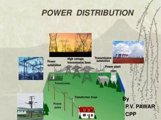
How are Harmonics Produced ? • Power system harmonics: presenting deviations from a perfect sinusoidal-waveform (voltage or current waveform). • The distortion comes from a Nonlinearity caused by saturation, electronic-switching and nonlinear electric loads, Inrush/Temporal/Arc/Converter/Limiter/Threshold Type Loads. Figure: 2 [1] EE 6633 Seminar 1
Why Bother about Harmonics? • 50-60% of all electrical Ac Systems in North America operate with non-linear type loads • Power-Quality-PQ Issues & Problems • Damage to Power Factor Correction capacitors • Waveform Distortion can create SAG/SWELL/NOTCHING/RINGING/… • All can cause damage effects to consumer loads and power systems due to Over-Current/Over-Voltage or Waveform Distortion • Additional Power/Energy Losses EE 6633 Seminar 1
Loads Producing Harmonic Currents • Electronic lighting ballasts/Controls • Adjustable speed Motor-Drives • Electric Arc Welding Equipment • Solid state Industrial Rectifiers • Industrial Process Control Systems • Uninterruptible Power Supplies ( UPS )systems • Saturated Inductors/Transformers • LAN/Computer Networks EE 6633 Seminar 1
Current vs. Voltage Harmonics • Harmonic current flowing through the AC Power System impedance result in harmonic voltage-drop at the load bus and along the Feeder!! Figure: 3 [3] EE 6633 Seminar 1
How to QuantifyHarmonic Distortion? • Total Harmonic Distortion-THD: the contribution of all harmonic frequency Currents/Voltages to the fundamental current. [3] • The level of THD-for Current or Voltage is directly related to the frequencies and amplitudes of the Offending Quasi-Steady State persistent Harmonics. • Individual Distortion Factor-(DF)-h quantify Distortion at h –harmonic-order EE 6633 Seminar 1
Calculation of THD • THD: Ratio of the RMS of the harmonic content to the RMS of the Fundamental [3] (Eq-1) • Current THD-I (Eq-2) • Voltage THD-V (Eq-3) EE 6633 Seminar 1
Negative Effects of Harmonics • Overheating and premature failure of distribution transformers [1] • Increasing iron and copper losses or eddy currents due to stray flux losses • Overheating and mechanical oscillations in the motor-load system [1] • Producing rotating magnitude field, which is opposite to the fundamental magnitude field. • Overheating and damage of neutral ground conductors [2] • Trouble sustained type Harmonics: 3rd, 9th, 15th … • A 3-phase 4-wire system: single phase harmonic will add rather than cancel on the neutral conductor • Malfunction/Mal-Operation of Sensitive Tele-control and Protection Relaying EE 6633 Seminar 1
Negative Effects of Harmonics (cont’ d) • False or spurious Relay operations and trips of circuit breakers [2] • Failure of the Firing/Commutation circuits, found in DC motor-drives and AC drives with silicon controlled rectifiers (SCR-Thyristor) [1] • Mal-Operation instability of voltage regulator [1] • Power factor correction capacitor failure [1] • Reactance (impedance)-Zc of a capacitor bank decreases as the frequency increases. • Capacitor bank acts as a sink for higher harmonic currents. • The System-Series and parallel Resonance can cause dielectric failure or rupture the power factor correction capacitor failure due to Over-Voltages & Over-Currents. EE 6633 Seminar 1
Harmonics and Parallel Resonance Circuit • Harmonic currents produced by variable speed motor-drives: can be amplified up to 10-15 times in parallel resonance circuit formed by the capacitance bank and network inductance[5] • Amplified/intensified harmonic currents: leading to internal overheating of the capacitor unit. • Higher frequency currents: causing more losses than 60hz currents having same amplitude Figure 4: Parallel resonance circuit and its equivalent circuit[5] EE 6633 Seminar 1
Harmonics and Series Resonance Circuit • The voltage of upstream AC Network can be also distorted due to series/parallel resonance formed by capacitance of the capacitor bank and System/load inductance : Ca cause high harmonic current circulation through the capacitors[5] • Parallel Resonance can also lead to high voltage distortion. Figure 5: Series resonance circuit and its equivalent circuit [5] EE 6633 Seminar 1
Measure Equipments of Harmonics • Digital Oscilloscope: Wave shape, THD and Amplitude of each harmonic • “True RMS” Multi-Meter: Giving correct readings for distortion-free sine waves and typically reading low when the current waveform is distorted Use of Harmonic Meters-Single Phase or three Phase Figure 6: “True RMS” Multi-Meter[3] EE 6633 Seminar 1
Standards for Harmonics LimitationIEEE/IEC • IEEE 519-1992 Standard: Recommended Practices and Requirements for Harmonic Control in Electrical Power Systems(Current Distortion Limits for 120v-69kv DS) Table 1: Current Harmonic Limits [4] EE 6633 Seminar 1
Standard of Harmonics Limitation (cont’d) • IEEE 519-1992 Standard: Recommended Practices and Requirements for Harmonic Control in Electrical Power Systems(Voltage Distortion Limits) Table 2: Voltage Harmonic Limits[4] EE 6633 Seminar 1
Mitigation Of Harmonics [1] • Ranging from variable frequency motor- drive to other nonlinear loads and equipments • Power System Design: • Limiting the non-linear load penetration to 30% of the maximum transformer’s capacity • Limiting non-linear loads to 15% of the transformer’s capacity, when power factor correction capacitors are installed. • Avoiding/Detuning resonant conditions on the AC System: (Eq-4) hr = resonant frequency as a multiple of the fundamental frequency kVAsc = short circuit current as the point of study kVARc = capacitor rating at the system voltage EE 6633 Seminar 1
Mitigation the Effects of Harmonics [1] (cont’d) • Delta-Delta and Delta-Wye Transformers • Using two separate utility feed transformers with equal non-linear loads • Shifting the phase relationship to various six-pulse converters through cancellation techniques Figure 7: Delta-Delta and Delta-Wye Transformers [1] EE 6633 Seminar 1
Mitigation the Effects of Harmonics [1] (cont’d) • Isolation-Interface Transformers • The potential to “voltage match” by stepping up or stepping down the system voltage, and by providing a neutral ground reference for nuisance ground faults • The best solution when utilizing AC or DC drives that use SCR/GTO/SSR.. as bridge rectifiers • Line Isolation-Reactors • More commonly used for their low cost • Adding a small reactor in series with capacitor bank forms a Blocking series Filter. • Use diode bridge rectifier as a front end to avoid severe harmonic power quality problems EE 6633 Seminar 1
Mitigation the Effects of Harmonics [1] (cont’d) • Harmonic-Shunt or Trap Filters: • Used in applications with a high non-linear ratio to system to eliminate harmonic currents • Sized to withstand the RMS current as well as the value of current for the harmonics • Providing true distortion power factor correction Figure 8: Typical Harmonic Trap Filter [1] EE 6633 Seminar 1
Harmonic Trap Filters (cont’d) • Tuned to a specific harmonic order such as the 5th, 7th, 11th,… etc to meet requirements of IEEE 519-1992 Standard • The number of tuned filter-branches depends on the offending steady-state harmonics to be absorbed and on required reactive power level to be compensated Figure 9: Typical Filter Capacitor Bank [5] EE 6633 Seminar 1
Harmonics Filter Types [6] • Isolating harmonic current to protect electrical equipment from damage due to harmonic voltage distortion • Passive Filter-Low cost: • Built-up by combinations of capacitors, inductors (reactors) and resistors • most common and available for all voltage levels • Active Power Filter APF: • Inserting negative phase compensating harmonics into the AC-Network, thus eliminating the undesirable harmonics on the AC Power Network. • APF-Used only for for low voltage networks EE 6633 Seminar 1
Harmonic Filter Types (cont’d) [7] • Unified Switched Capacitor Compensator USCS: The single line diagram (SLD) of the utilization (single-phase) or (three-phase- 4-wire) feeder and the connection of the Unified Switched- Capacitor Compensator (USCS) to the Nonlinear-Temporal Inrush /Arc type Loads or SMPS-Computer/LAN-Network loads. Figure 10 [7] EE 6633 Seminar 1
Harmonics Filter Types (cont’d) [7] • The USCS is a switched/modulated capacitor bank using a pulse-width modulated (PWM/SPWM) Switching Strategy. The switching device uses either solid state switch SSR-(IGBT or GTO). Figure 11[7] EE 6633 Seminar 1
Need To Evaluate System Harmonics? [1] • The application of capacitor banks in systems where 20% or more of the load includes other harmonic generating equipment. • The facility has a history of harmonic related problems, including excessive capacitor fuse operation or damage to sensitive metering/relaying/control equipment. • During the Planning/Design stage of any facility comprising capacitor banks and nonlinear harmonic generating equipment. EE 6633 Seminar 1
When to Evaluate System Harmonics? [1] (cont’d) • In facilities where restrictive Electric Power Utility Company Standards/Guidelines limit the harmonic injection back into their system to very small magnitudes. • Industrial/Commercial Plant expansions that add significant harmonic generating nonlinear type equipment operating in conjunction with capacitor banks. • When coordinating and planning to add any emergency standby generator as an alternate/renewable power source EE 6633 Seminar 1
Conclusions • The harmonic distortion principally comes from Nonlinear-Type Loads. • The application of power electronics is causing increased level of harmonics due to Switching!! • Harmonic distortion can cause serious Failure/Damage problems. • Harmonics are important aspect of power operation that requires Mitigation!! • Over-Sizing and Power Filtering methods are commonly used to limit Overheating Effects of Sustained Harmonics. EE 6633 Seminar 1
References [1] www-ppd.fnal.gov/EEDOffice-w/Projects/CMS/LVPS/mg/8803PD9402.pdf [2] www.pge.com/docs/pdfs/biz/power_quality/power_quality_notes/harmonics.pdf [3] www.metersandinstruments.com/images/power_meas.pdf [4]http://engr.calvin.edu/PRibeiro_WEBPAGE/IEEE/ieee_cd/chapters/CHAP_9/c9toc/c9_frame.htm [5] www.nokiancapacitors.com.es/.../EN-TH04-11_ 2004- Harmonics_and_Reactive_Power_Compensation_in_Practice.pdf [6]http://rfcomponents.globalspec.com/LearnMore/Communications_Networking/RF_Microwave_Wireless_Components/Harmonic_Filters [7]A.M. Sharaf & Pierre Kreidi, POWERQ UALITYE NHANCEMEUNSTI NGA UNIFIEDSW ITCHED CAPACITOCRO MPENSATOR, CCECE 2003 - CCGEI 2003, Montreal, Mayimai 2003 0-7803-7781-8/03/$17.00 0 2003 IEEE EE 6633 Seminar 1
Question ? EE 6633 Seminar 1