Download
1 / 4
40 likes | 41 Views
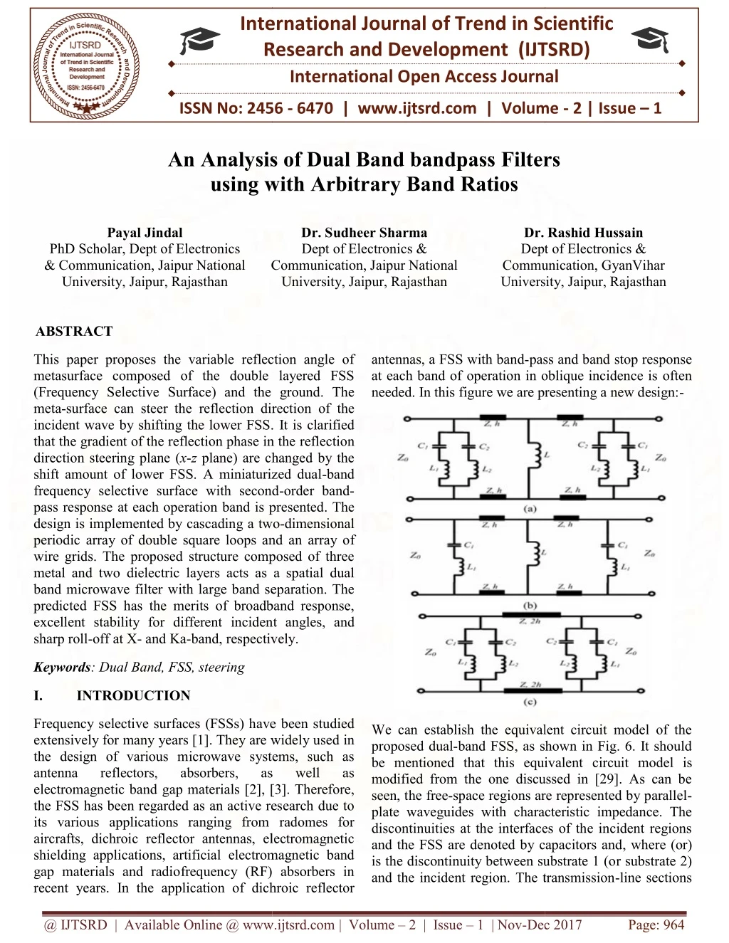
This paper proposes the variable reflection angle of meta surface composed of the double layered FSS Frequency SelectiveSurface and the ground. The meta surface can steer the reflection direction of the incident wave by shifting the lower FSS. It is clarified that the gradient of the reflection phase in the reflection direction steering plane x z plane are changed by the shift amount of lower FSS. A miniaturized dual band frequency selective surfaces with second order band pass response at each operation band is presented. The design is implemented by cascading a two dimensional periodic array of double square loops and an array of wire grids. The proposed structure composed of three metal and two dielectric layers acts as a spatial dual band microwave filter with large band separation. The predicted FSS has the merits of broadband response, excellent stability for different incident angles, and sharp roll off at X and Ka band, respectively.Key words Dual Band, FSS, steering etc. Payal Jindal | Dr. Sudheer Kumar Sharma | Dr. Rashid Hussain "An Analysis of Dual Band bandpass Filters using with Arbitrary Band Ratios" Published in International Journal of Trend in Scientific Research and Development (ijtsrd), ISSN: 2456-6470, Volume-2 | Issue-1 , December 2017, URL: https://www.ijtsrd.com/papers/ijtsrd7102.pdf Paper URL: http://www.ijtsrd.com/engineering/electronics-and-communication-engineering/7102/an-analysis-of-dual-band-bandpass-filters-using-with-arbitrary-band-ratios/payal-jindal<br>

E N D
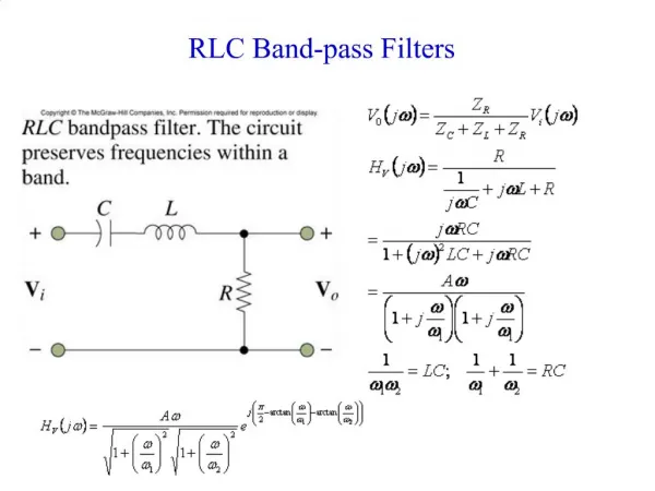
International Research Research and Development (IJTSRD) International Open Access Journal International Open Access Journal International Journal of Trend in Scientific Scientific (IJTSRD) ISSN No: 2456 - 6470 | www.ijtsrd.com | Volume An Analysis of Dual Band bandpass Filters An Analysis of Dual Band bandpass Filters ISSN No: 2456 | www.ijtsrd.com | Volume - 2 | Issue – 1 An Analysis of Dual Band bandpass Filters using with Arbitrary Band Ratios sing with Arbitrary Band Ratios Payal Jindal Dr. Sudheer Sharma Dept of Electronics & Dr. Rashid Hussain Dept of Electronics & Communication, GyanVihar University, Jaipur, Rajasthan University, Jaipur, Rajasthan Dr. Rashid Hussain Dept of Electronics & Communication, GyanVihar PhD Scholar, Dept of Electronics & Communication, Jaipur National University, Jaipur, Rajasthan Communication, Jaipur National Communication, Jaipur National University, Jaipur, Rajasthan ABSTRACT This paper proposes the variable reflection angle of metasurface composed of the double layered FSS (Frequency Selective Surface) and the ground. The meta-surface can steer the reflection direction incident wave by shifting the lower FSS. that the gradient of the reflection phase in the direction steering plane (x-z plane) are changed by the shift amount of lower FSS. A miniaturized dual frequency selective surface with second pass response at each operation band is presented. The design is implemented by cascading a two periodic array of double square loops and an wire grids. The proposed structure composed of three metal and two dielectric layers acts as a spatial dual band microwave filter with large band separation. The predicted FSS has the merits of broadband response, excellent stability for different incident angles, and sharp roll-off at X- and Ka-band, respectively. band, respectively. This paper proposes the variable reflection angle of composed of the double layered FSS Surface) and the ground. The antennas, a FSS with band-pass and band at each band of operation in oblique incidence is needed. In this figure we are presenting a new design: ure we are presenting a new design:- pass and band stop response at each band of operation in oblique incidence is often reflection direction of the incident wave by shifting the lower FSS. It is clarified that the gradient of the reflection phase in the reflection plane) are changed by the shift amount of lower FSS. A miniaturized dual-band with second-order band- band is presented. The a two-dimensional periodic array of double square loops and an array of wire grids. The proposed structure composed of three dielectric layers acts as a spatial dual filter with large band separation. The the merits of broadband response, incident angles, and Keywords: Dual Band, FSS, steering I. INTRODUCTION Frequency selective surfaces (FSSs) have been studied extensively for many years [1]. They are widely used the design of various microwave systems, such as antenna reflectors, absorbers, electromagnetic band gap materials [2], [3]. Therefore, the FSS has been regarded as an active research due to its various applications ranging from radomes for aircrafts, dichroic reflector antennas, electromagnetic shielding applications, artificial electromagnetic band gap materials and radiofrequency (RF) absorbers in recent years. In the application of dichroic reflector requency selective surfaces (FSSs) have been studied extensively for many years [1]. They are widely used in the design of various microwave systems, such as reflectors, absorbers, gap materials [2], [3]. Therefore, FSS has been regarded as an active research due to applications ranging from radomes for reflector antennas, electromagnetic e can establish the equivalent circuit model of the band FSS, as shown in Fig. 6. It should be mentioned that this equivalent circuit model is modified from the one discussed in [29]. As can be space regions are represented by parallel- plate waveguides with characteristic impedance. The discontinuities at the interfaces of the incident regions and the FSS are denoted by capacitors and, where (or) is the discontinuity between substrate 1 (or substrate 2) We can establish the equivalent circuit model of the proposed dual-band FSS, as shown in Fig. 6. It should be mentioned that this equivalent modified from the one discussed in [29]. As can be seen, the free-space regions are represented by parallel plate waveguides with characteristic impedance. The discontinuities at the interfaces of the incident regions and the FSS are denoted by capacitors and is the discontinuity between substrate 1 (o and the incident region. The transmission and the incident region. The transmission-line sections as as well well as as electromagnetic band gap materials and radiofrequency (RF) absorbers in dichroic reflector @ IJTSRD | Available Online @ www.ijtsrd.com @ IJTSRD | Available Online @ www.ijtsrd.com | Volume – 2 | Issue – 1 | Nov-Dec 2017 Dec 2017 Page: 964
and represent the propagation path 1, where is equivalent to the middle cavity, and is the narrow gap between the top- and middle-layer strip lines. It is the inductance of the metallic rod and via hole1 in path 1. The transmission-line section denotes the propagation path 2, is the inductance of via hole2 in path 2. The result of required designs are shown below:- International Journal of Trend in Scientific Research and Development (IJTSRD) ISSN: 2456-6470 In this design, we only assume that the plane of incidenceis in the -plane and the electric field is parallel to the -axis, namely TE-polarization incidence. Fig. 3 provides the simulated S-parameter results of a design example by using a commercial full-wave simulator CST microwave Studio (CST-MWS). It is observed that two pass bands are obtained around (3 GHz) and (13.5 GHz), respectively. In the lower frequency band, two transmission poles are achieved at 2.82 GHz and 3.1GHz. In the higher frequency band, another two transmission poles are realized at 13.3 GHz and 13.8 GHz .The frequency band ratio is as large as 4.5. Due to the large band ratio, the maximum isolation between these two operating bands can reach 40 dB. The detailed operating principle can be explained by the electric field distributions and an equivalent circuit model in the following sections. There are several techniques in designing dual- or multi-band frequency-selective literature, which can be summarized as: 1) multi- layered structures perturbations of a single-band FSS [11]–[13] or loading extra resonant elements [14], [15]; 3) fractal elements [16], [17]; 4) multi-resonant elements, such as double complementary patterns [18]–[23], and so on. Most of the existing designs are focused on the application of close frequency band spacing. Thus, the band ratios of their operating frequencies are usually not more than 3 in [8]–[23]. It may be true that a dual- or multi-band frequency-selective surface with a small band ratio is desirable for a lot of applications. However, it is still a challenge for the existing designs to obtain excellent dual- or multi-band responses with large band ratios because of the appearances of harmonic resonances and grating lobes. Moreover, the angular-stability of most dual- or multi-band frequency-selective surfaces will deteriorate rapidly when the frequency band ratio is large. surfaces in the square loops and It is undesirable that there is a spurious resonance that creeps into the second band from the upper side as the incident angle increases. This is because that the second pass band is formed by the coupling between the serial resonator and serial resonators. In fact, the upper side frequency region of the second band is just the high- order resonant frequency band of serial resonator. Consequently, as the incident angle increased, the @ IJTSRD | Available Online @ www.ijtsrd.com | Volume – 2 | Issue – 1 | Nov-Dec 2017 Page: 965
grating gradually creeps into the second band from the upper side. International Journal of Trend in Scientific Research and Development (IJTSRD) ISSN: 2456-6470 transmission poles in each operating frequency band. The operating principle has been explained by analyzing the electric establishing the equivalent circuit model. In order to verify our concept, two design example with band ratios of 4.2and 1.95 have been fabricated and measured. The measured results show that the proposed FSS exhibits stable dual-band performance with arbitrary band spacing under a large variation of incident angle. Although the proposed FSS is limited for single polarization, the presented concept may be readily extended to realize a dual-polarized FSS, which may be the topic of a future publication. field distributions and II. ELECTRIC FIELD DISTRIBUTIONS AND EQUIVALENTCIRCUIT MODEL A.Electric Field Distributions Assuming that the left- and right-side free-space regions representing the incoming plane wave in Fig. 1 are the input port(port 1) and output port (port 2), respectively. Signals can pass through the whole structure in the two operating pass bands. Fig. 4 illustrates the electric field distributions (in the -plane) at four transmission-pole frequencies. At frequencies and the frequency response of TM mode remains stable as the angle increases. The difference above can be explained as follows. The electrical length of FSS element is different for different polarization resulting resonant frequency and the different bandwidth when the incident angle is relative large[5].The frequency response in upper reflection band under different angles and polarizations is shown in Fig. 5 and there sonant frequency is about 44 GHz. As observed, the structure of FSS demonstrates a rather stable response as a function of incidence angle in the upper frequency band for both the TE and TM mode wave. From the transmission coefficient curves in Fig. 5, it can be seen that the -30dBbandwidth is rather broad when the angle is 0° for TE and TM mode. An inevitable fact occurs that the bandwidth narrows as the angle increases. REFERENCES 1.E. Pelton and B.Munk, “A streamlined metallic radome,” IEEE Trans.Antennas Propag., vol. AP- 22, no. 6, pp. 799–803, Nov. 1974. 2.J. A. Encinar, “Design of two-layer printed reflectarrays using patchesof variable size,” IEEE Trans. Antennas Propag., vol. 49, no. 10, pp.1403– 1410, Oct. 2001. 3.G. Sung, K. W. Sowerby, M. J. Neve, and A. G. Williamson, “A frequency-selective wall for interference reduction environments,”IEEE Antennas Propag. Mag., vol. 48, no. 5, pp. 29–37,Oct. 2006. 4.M. Li and N. Behdad, “Frequency selective surfaces for high powermicrowave applications,” IEEE Trans. Antennas Propag., vol. 61, no.2, pp. 677– 687, Feb. 2013. 5.S. Chakravarty, R. Mittra, and N. R. Williams, “On the application ofthe microgenetic algorithm to the design of broad-band comprising frequency-selective surfaces embedded in multilayered dielectric media,” IEEE Trans. Microw. Theory Tech., vol. 49,no. 6, pp. 1050– 1059, Jun. 2001. 6.S. A. Winkler, W. Hong,M. Bozzi, and K.Wu, “Polarization rotatingfrequency selective surface based on waveguidetechnology,” IEEE Trans. Antennas Propag., vol. 58, no. 4, pp.1202–1213, Apr. 2010. 7.R. A. Hill and B. A. Munk, “The effect of perturbating a frequencyselective surface and its relation to the design of a dual-band surface,”IEEE Trans. Antennas Propag., vol. 44, no. 3, pp. 368– 374, Mar. 1996. 8.R. R. Xu, H. C. Zhao, Z. Y. Zong, and W. Wu, “Dual-band capacitiveloaded frequency selective surfaces with close band spacing,” IEEEMicrow. Wireless Compon. Lett., vol. 18, no. 12, pp. 782– in wireless indoor microwave absorbers substrate integrated IV. CONCLUSION In this paper, a second-order dual-band FSS is designed. The predicted FSS has the merits of small element size, dual independent operating band at X- and Ka-band, higher selectivity and broadband response. The qualitative analysis is presented by the equivalent circuit model. In each propagation path, two resonators are constructed, thus leading two @ IJTSRD | Available Online @ www.ijtsrd.com | Volume – 2 | Issue – 1 | Nov-Dec 2017 Page: 966
International Journal of Trend in Scientific Research and Development (IJTSRD) ISSN: 2456-6470 20.X.-D. Hu, X.-L. Zhou, L.-S. Wu, L. Zhou, and W.- Y. Yin, “A miniaturizeddual-band frequency selective surface (FSS) with closed loopand its complementary pattern,” IEEE AntennasWireless Propag. Lett.,vol. 8, pp. 1374–1377, 2009. 21.G. Q. Luo, W.Hong,H. J. Tang, J.X. Chen, andK.Wu, “Dual-band frequency-selective surfaces using substrate-integrated technology,”IETMicrow. Antennas Propag., vol. 1, no. 2, pp. 408–413,2007. 22.G. Q. Luo, W. Hong, H. J. Tang, J. X. Chen, and L. L. Sun, “Tribandfrequency selective surfaces with periodic cell perturbation,” IEEE Microw.Wireless Compon. Lett., vol. 17, no. 6, pp. 436–438, 2007. 23.A. K. Rashid and Z. Shen, “A novel band-reject frequency selectivesurface with pseudo-elliptic response,” IEEE Trans. Antennas Propag.,vol. 58, no. 4, pp. 1220–1226, Apr. 2010. 24.X. Huang, C. Yang, Z. Lu, and P. Liu, “A novel frequency selectivestructure with quasi-elliptic bandpass response,” WirelessPropag. Lett., vol. 11, pp. 1497–1500, 2012. 25.A. K. Rashid, Z. Shen, and B. Li, “An elliptical bandpass frequencyselective structure based on microstrip lines,” IEEE Trans. AntennasPropag., vol. 60, no. 10, pp. 4661–4669, Oct. 2012. 26.C. Pelletti, G. Bianconi, R. Mittra, and Z. Shen, “Frequency selectivesurface with wideband quasi- elliptic bandpass response,” Electron.Lett., vol. 49, no. 17, pp. 1052–1053, 2013. 27.B. Li and Z. Shen, “Angular-stable and polarization-independent structure with high selectivity,” Appl. Phys. Lett., vol.103, no. 17, p. 171607, 2013. 28.B. Li and Z. Shen, “Three-dimensional bandpass frequency selectivestructures transmission zeros,” IEEE Trans. Microw.Theory Tech., vol. 61, no. 10, pp. 3678–3589, Oct. 2013. 29.B. Li and Z. Shen, “Three-dimensional dual- polarized bandpassfrequency selective structures with wide out-of-band rejection,” IEEETrans. Antennas Propag., vol. 62, no. 1, pp. 130–137, Jan. 2014. 30.B. Li and Z. Shen, “Bandpass frequency selective structure with widebandspurious rejection,” IEEE Antennas Wireless Propag. Lett., vol.13, pp. 145– 148, 2014. 31.B. Li and Z. Shen, “Dual-band frequency selective structure with largefrequency band ratio,” in Proc. IEEE MTT-S Int. Microw. WorkshopSer. RF and Wireless Technol. Biomed. Healthcare Applicat. (IMWSBIO),2013, pp. 1–3. 784, Dec.2008. 9.N. Behdad, M. A. Joumayly, and M. Salehi, “A low-profile third-orderbandpass frequency selective surface,” IEEE Trans. Antennas Propag.,vol. 57, no. 2, pp. 460–466, Feb. 2009. 10.M. A. Joumayly and N. Behdad, “A new technique for design of lowprofile,second-order, bandpass frequency selective surfaces,” IEEETrans. Antennas Propag., vol. 57, no. 2, pp. 452–459, Feb. 2009. 11.M. Salehi and N. Behdad, “A second-order dual X- /Ka-band frequencyselective Microw. Wireless Compon. Lett., vol. 18, no.12, pp. 785–787, Dec. 2008. 12.R. J. Langley and E. A. Parker, “Double-square frequency-selectivesurfaces and their equivalent circuit,” Electron. Lett., vol. 19, no. 17,pp. 675– 677, 1983. 13.K. Sarabandi and N. Behdad, “A frequency selective surface withminiaturized elements,” IEEE Trans. Antennas Propag., vol. 55, no.5, pp. 1239– 1245, May 2007. 14.C. K. Lee and R. J. Langley, “Equivalent-circuit models for frequencyselective surfaces at oblique angles of incidence,” Proc. Inst. Electr.Eng. H, Microw., Antennas, Propag., vol. 132, no. 6, pp. 395–399,1985. 15.Y. Pang, H. Cheng, Y. Zhou, and J. Wang, “Analysis and design ofwire-based metamaterial absorbers using equivalent circuit approach,”J. Appl. Phys., vol. 113, no. 114902, 2013. 16.Z. L. Wang, K. Hashimoto, N. Shinohara, and H. Matsumoto, “Frequency-selective microwave power transmission,” Microw. Theory Tech., vol. 47, no. 10, pp. 2039– 2042, Oct.1999. 17.J.A.Bossard,D.H.Werner, T. S. Mayer, J. A. Smith, Y. U. Tang,R. P.Drupp, and L. Li, “The design and fabrication of metallodielectricfrequency selective surfaces for infrared applications,”IEEE Propag., vol. 54, no. 4, pp. 1265–1276, Mar.2006. 18.T.-K.Wu and S.-W. Lee, “Multiband frequency surface with multiringpatch elements,” IEEE Trans. Antennas Propag., vol. 42, no. 11, pp.1484–1490, Nov. 1994.[19] T.-K. Wu, “Four-band frequency selective surface with double squareloop patch elements,” IEEE Trans. Antennas Propag., vol. 42, no. 12,pp. 1659–1663, Dec. 1994. 19.A. D. Chuprin, E. A. Parker, and J. C. Batchelor, “Convoluted doublesquare: Single layer FSS with close band spacings,” Electron. Lett.,vol. 36, no. 22, pp. 1830–1831, 2000. waveguide surface,” IEEE IEEE Antennas surface IEEETrans. for frequencyselective with multiple planar multiband Trans. Antennas @ IJTSRD | Available Online @ www.ijtsrd.com | Volume – 2 | Issue – 1 | Nov-Dec 2017 Page: 967