Download
1 / 39
430 likes | 677 Views
Band Gap Regulator Analysis. J. R. Biard, Ph.D. Honeywell 9/10/02. 1. Silicon Band Gap. The band gap of silicon changes with temperature Between -40 o C and 200 o C this can be fit with a linear equation to within ± 1.5meV. 2. Silicon Band Gap. 3.

E N D
Band Gap Regulator Analysis J. R. Biard, Ph.D. Honeywell 9/10/02 1
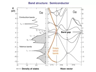
Silicon Band Gap • The band gap of silicon changes with temperature • Between -40oC and 200oC this can be fit with a linear equation to within ± 1.5meV 2
Transistor Equation • For an NPN bipolar transistor the collector current is given by 4
Transistor Equation • Combining these expressions gives 5
Transistor Equation • The intrinsic carrier density expressed in terms of the linear fit to the band gap is given by 6
Transistor Equation • Between -40oC and 200oC the intrinsic carrier concentration is given by • Thus, silicon behaves as though it had a constant band gap of EGo. Constant band gap is used in PSPICE but the default value is wrong (1.11eV). 7
Transistor Equation • Silicon mobility follows a power law with absolute temperature; the exponent is a function of the doping level. • The same general form also works for P-type material 8
Transistor Equation • A 2000 /sq P-type resistor is PTAT - Proportional To Absolute Temperature. • This resistor gives a constant collector current in a band gap regulator. • All other resistors require a temperature dependent collector current. 9
Transistor Equation • Combining all these equations gives the form of the transistor equation needed for the band gap regulator 10
Differential Equation • Taking the derivative of the transistor equation with respect to temperature gives a differential equation • This nonlinear differential equation can be solved using an integration factor. 11
Differential Equation • Solve the differential equation for Vbe Where Vbeo is the value of Vbe @ To • Vbe is a linear function of T only when (4 + - ) = 0. 12
Transistor Model • In PSPICE the term (4 - ) is called XTI, EGo is called EG and must be set to EG = 1.2058; PSPICE uses 1.11. • Modeling Honeywell NPN transistors for PSPICE with EG = 1.2058 and = 0 gives XTI = 2.0599. • = 4 - 2.0599 = 1.9401 13
Transistor Model • For IC = 100A and To = 298oK (25oC) linear regression of Vbe data between -40oC and 200oC gives: • The error between measured Vbe and the best straight line fit over temperature is ±2.0mV 14
Band Gap Regulator • For a PTAT resistor in series with a diode connected transistor biased to Vref the drop across the resistor is PTAT regardless of the value of the resistor. • For a zero TC resistor the resistor current and voltage are both PTAT, b = 1, Vref is different, and the variation with temperature is greater. 16
Band Gap Regulator • Vref = 1.2654V • PTAT Resistor • Resistor voltage is PTAT independent of resistor value. • @ 0.1mA, Vbe = 0.6701V • @ 1.0mA, Vbe = 0.7292V • (dVbe/dT) drops by 0.1984mV/oC 17
Band Gap Regulator PTAT Resistors 5.953K & 3.0K 18
Band Gap Regulator Implant Resistors 5.953K & 3.0K 19
Band Gap Regulator • The voltage difference between the Vbe values of two transistors operated at different current density has a positive linear temperature coefficient and Vbe has a nearly linear negative temperat-ure coefficient. These two characteris-tics can be combined to give a near zero temperature coefficient voltage source. 20
Differential Equation • Taking the derivative of the transistor equation with respect to temperature gives a differential equation • This nonlinear differential equation can be solved using an integration factor. 11
Band Gap Regulator • When the collector (emitter) current is changed by a factor of 10 at 298oK (25oC) the Vbe changes by 59.13mV and dVbe/dT changes by 0.1984mV/oC. • Thus, the difference in Vbe of two transistors operated at a 10/1 current density ratio is proportional to absolute temperature. 21
Band Gap Regulator • The band gap regulator is a compact analog computer that solves for a constant reference voltage (~EGo). • The +0.1984mV/oC temperature coef-ficient difference between two junctions operated at 10/1 current density must be multiplied by 10.070 to equal the dVbe/dT of -1.9978mV/oC. 22
Band Gap Regulator • The Vbe difference of 59.13mV @ 25oC must also be multiplied by 10.070 which gives a voltage of 0.5953V. • Adding this voltage to Vbeo = 0.6701V gives a reference voltage of 1.2654V. • This reference voltage is equivalent to Vref = EGo + 2.32(kTo/q) @ 25oC. 23
Band Gap Regulator • The positive TC voltage that must be added to the Vbe to get the reference voltage is proportional to absolute temperature. • With a 2000/sq implanted resistor which is proportional to absolute temperature the collector current is constant and = 0. 24
Band Gap Regulator • The deviation of Vref from its nominal value over the temperature range is of the order of the ±2.0mV deviation in the Vbe from the best straight line fit. • For smaller temperature ranges the best value of Vref is slightly different and the deviation from nominal is less. 25
Band Gap Regulator PTAT Resistors 29
Band Gap Regulator Implant Resistors 32
Summary • Know your circuit • What does it have to do? • Know your simulator • When do you take exception to defaults? • Characterize your devices in terms of the parameters used in your simulator • How were the measurements done? 37
PSPICE Models • PTAT Resistor .MODEL Rptat RES (r=1.0 tc1=3.3557e-3 tc2=0) • IMP Resistor .MODEL Rimp RES (r=1.0 tc1=3.6600e-3 tc2=7.0300e-6) • NPN Transistor with N+ sinker, 10mm x 10mm emitter .MODEL QNPN NPN (is=8.41E-17 bf=1.928e+2 nf=1.00e+0 + vaf=1.046e+2 ikf=7.85e-3 ise=1.056e-18 ne=1.091e+00 br=3.257e+1 + nr=1.00e+0 var=1.052e+1 ikr=2.2775e-3 isc=4.1715e-15 + nc=1.752e+0 nk=5.00e-1 iss=0.00e+0 ns=1.00e+0 re=1.1025e+0 + rb=5.1475e+2 rbm=1.072e+2 rco=0.00e+0 vo=1.8519e+0 + gamma=1.1586e-10 qco=2.3742e-14 cje=1.80e-13 vje=7.40e-1 + mje=3.40e-1 cjc=5.9584e-14 vjc=6.00e-1 mjc=4.00e-1 xcjc=1.00e+0 + cjs=2.9648e-14 vjs=5.00e-1 mjs=3.10e-1 fc=5.00e-1 tf=2.1e-10 + xtf=0.00e+0 vtf=1.00e+2 itf=0.00e+0 ptf=0.00e+0 tr=1.00e-8 + eg=1.20585e+0 xtb=1.905e+0 xti=2.0599e+0 kf=0.00e+0 af=1.00e+0 + tre1=6.64e-4 tre2=-4.72e-7 trb1=4.00e-3 trb2=8.00e-6 trm1=8.24e-4 + trm2=5.13e-6 trc1=7.02e-3 trc2=1.91e-5) 38