Download
1 / 96
960 likes | 962 Views
Summary of TRD pad plane, front-end boards and readout chain. David Emschermann GSI Darmstadt. Outline. TRD requirements MWPC geometry pad plane constraints 6 module types FEB types optimisation beyond TDR readout chain. TRD geometry v16b. The TRD geometry v16b

E N D
Summary of TRD pad plane, front-end boards and readout chain David Emschermann GSI Darmstadt
Outline • TRD requirements • MWPC geometry • pad plane constraints • 6 module types • FEB types • optimisation beyond TDR • readout chain
TRD geometry v16b The TRD geometry v16b described in the TDR: SIS 100 1 4 200 280 1384 1112 8992 287744 station layers modules ROBs GBTx FEBs 32ch ASICs channels
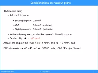
TRD requirements • pion suppression factor 10-20 > 6 GeV/c • (@ 90% e-efficiency) • position resolution of 200 – 300 μm • rate capability up to 100 kHz/cm² • capability to deal with high multiplicity
TRD layout • rectangular pads • MWPC modules of squared shape • modules rotated between neighboring layers • all services connected through the backside • 2 module sizes, 6 module types • 4 layers
2 TRD module sizes 2 different TRD module sizes outer inner 95 x 95 cm 57 x 57 cm TRD modules The small module is built from a single pad plane PCB. The maximum width the PCB manufacturer can handle is: 590 mm. We build pad planes of 580 mm x 580 mm size. The resulting small module size is 570 mm x 570 mm. The large module can be built from 2 PCB pieces.
Module size ratio The large module size is given by the layer design: 5 x small module = 3 x large module 5 x 570 mm = 3 x 950 mm
Pad plane material The TRD is a 360 μm thick 2-layer PCB with 25 μm thick Cu layers. PCBs are ordered from the same company as for the ALICE TRD production.
Pad length The pad length is an integer multiple of the anode wire pitch. The edge of a pad ends between 2 anode wires. This allows for minimal charge sharing between pad rows.
TRD modules – 90° rotated odd layers (1,3) even layers (2,4) vertical pads horizontal pads good resolution in y good resolution in x here: 7.5mm x 30mm pad size
Pad sectors in TRD modules layer 1 layer 2 sector A sector B good y-resolution sector A good x-resolution A module can contain pads of different size, they have a fixed width (6.75mm for small modules, 7.12mm for large modules) but may differ in height.
TRD wire geometry TRD 3.5/3.5/5 7/2 7/2 5 signal collection time Data readout 255 ns 230 ns 210 ns TRD 3/3/6 TRD 3.5/3.5/5 TRD 4/4/4 A A D 42% drift 12 mm thickness signal collection in Xe/CO2 (80/20), @ 100V/mm drift
Pad response function We have aimed at a signal distribution of 10-80-10% between the central and neighboring pads, which is achieved according to beam test data from 2015, see PRF function on the left side.
TRD hit rates RICH v08a TRD trigger rates with legacy RICH v08a (small amount of material upstream)
TRD hit rates RICH v14a TRD trigger rates with RICH v14a (larger amount of material due to modified support struture)
Type 1 pad plane v16b • 36 rows, 80 columns • 2880 pads • 1.01 cm² pad size • 45x 64-pin connectors • 5 connectors per row • 4 rows per connector
Type 1 pad block v16b • channel sequence • determined by • angular pad order • identical pattern • for all footprints of • a given module type • all vias within a pad • row are along a • straight line (simpler • to seal with glue • for gas tightness) • 16 pads block width • 4 rows a 16 pads = 64 pads
64ch signal cable connection • 64-pin connectors • are solderd to the • pad plane • flat cables are used • to connect to the • electonics • 64-pin cables • interface to • 2x 32ch-SPADICs 64 pin cable 0.5 mm pitch AXON FFC 0.50 A 64 / 0150 S 3,5-3,5-08,0-08,0 F AJJ / N
Module type 1 FEBs • 2880 channels • 45x cable connections • 9 FEBs a 5x2 ASICs • 2x GBTx ROB-7 • 16 optical links • 2x down- 14x uplink • 180/196 e-links used • 92% uplink efficiency
Type 2 pad plane v16b • 20 rows, 80 columns • 1600 pads • 1.69 cm² pad size • 25x 64-pin connectors • 5 connectors per row • 4 rows per connector
Module type 2 FEBs • 1600 channels • 25x cable connections • 5 FEBs a 5x2 ASICs • 1x GBTx ROB-3 • 1x GBTx ROB-5 • 10 optical links • 2x down- 8x uplink • 100/112 e-links used • 89% uplink efficiency
Type 3 pad plane v16b • 12 rows, 80 columns • 960 pads • 3.04 cm² pad size • 30x 32-pin connectors • 5 connectors per row • 2 rows per connector
Type 3 pad block v16b This type of connector layout is also used on all large detectors, module types 6,7,8
32ch signal cable connection • 40-pin connectors • (for historical • reasons) • are solderd to the • pad plane • flat cables are used • to connect to the • electonics • 40-pin cables • interface to • 1x 32ch-SPADIC 40 pin cable 0.5 mm pitch AXON FFC 0.50 A 40 / 0046 L 4.0-4.0-22.0-08.0 S ABB
Module type 3 FEBs • 960 channels • 30x cable connections • 6 FEBs a 5x1 ASICs • 1x GBTx ROB-5 • 6 optical links • 1x down- 5x uplink • 60/70 e-links used • 86% uplink efficiency
Type 6 pad plane v16b • 16 rows, 128 columns • 2048 pads • 4.13 cm² pad size • 64x 32-pin connectors • 8 connectors per row • 2 rows per connector
Module type 6 FEBs • 2048 channels • 64x cable connections • 8 FEBs a 8x1 ASICs • 2x GBTx ROB-5 • 12 optical links • 2x down- 10x uplink • 128/140 e-links used • 91% uplink efficiency
Type 7 pad plane v16b • 8 rows, 128 columns • 1024 pads • 8.27 cm² pad size • 32x 32-pin connectors • 8 connectors per row • 2 rows per connector
Module type 7 FEBs • 1024 channels • 32x cable connections • 4 FEBs a 8x1 ASICs • 1x GBTx ROB-5 • 6 optical links • 1x down- 5x uplink • 64/70 e-links used • 91% uplink efficiency
Type 8 pad plane v16b • 6 rows, 128 columns • 768 pads • 10.96 cm² pad size • 24x 32-pin connectors • 8 connectors per row • 2 rows per connector
768 channels • 24x cable connections • 3 FEBs a 8x1 ASICs • 1x GBTx ROB-3 • 4 optical links • 1x down- 3x uplink • 24/42 e-links used • (only 1 e-link per Spadic) • cannot be done with • Spadic v2.0 • 57% uplink efficiency Module type 8 FEBs
90/9/15/3 50/5/8/2 30/6/5/1 TRD geometry v16b 64/8/10/2 32/4/5/1 24/3/3/1
TRD v17a - Reduction of FEB types
Type 3 v17a modification => Replace FEB 5x1 which only occurs on module type 3 by FEB 5x2 To reduce FEB diversity.
Pad plane type 3 v17a => Instead of 2, read 4 rows per connector. This leads to longer wire traces on the pad plane, larger capacity and slight noise increase. It saves 1 FEB type.
90/9/15/3 60/6/10/2 30/3/5/1 TRD geometry v17a 64/8/10/2 32/4/5/1 16/2/3/1
GBTx ROBs for TRD ROB-3 1130 CHF 161/ch
GBTx ROBs for TRD 550 CHF 183/ch Joerg GBTx ROB-3 42 e-ports Lehnert 840 CHF 168/ch GBTx ROB-5 70 e-ports 1130 CHF 161/ch GBTx ROB-7 98 e-ports