Download
1 / 71
710 likes | 719 Views
A presentation to the QCWA Chapter 70 about Lightning and Grounding. Many of the following slides courtesy of. Todd Sirola C.O.O. SAE Inc. Todd provided a presentation to the CCBE last fall on the following topics Threats To Equipment Grounding Fundamentals

E N D
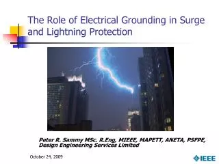
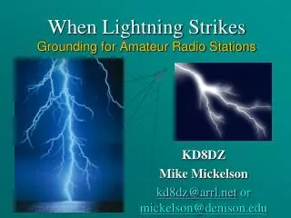
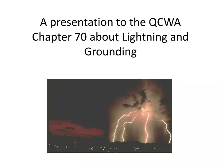
A presentation to the QCWA Chapter 70 about Lightning and Grounding
Many of the following slides courtesy of Todd Sirola C.O.O. SAE Inc. Todd provided a presentation to the CCBE last fall on the following topics Threats To Equipment Grounding Fundamentals Electrical Protection Systems Case Studies
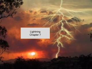
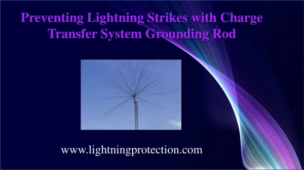
How do we get lightning? • We need convection, cumulo-nimbus clouds, the ones with the anvil shape, the result of a collision of warm and cold air masses • Ice pellets and grauple • Super cooled water droplets above the freezing level • Earth has a positive charge, the bottom of the cloud negative charge • Air is a great insulator so the charges build up
At some point the charge is large enough to overcome the insulator • The leaders build out slowly at relatively low current in both directions • Once they join the current flows. Upwards of 400,000 amps peak • Power levels in excess of 1 Gigawatt may be encountered • Systems need to be engineered with this in mind
lightning can, and often does, strike the same spot more than once--even the same person. U.S. park ranger Roy Sullivan reportedly was struck seven times between 1942 and 1977. • Take especially swift action if your hair stands on end, as that means charged particles are starting to use your body as a pathway.
Just remember Lightning energy and power system ground faults will find a path to earth. The key is to design an electrical protection system to ensure it doesn’t damage equipment.
Branches Electrical representation of a tree Trunk Roots
Types of Lightning • Cloud to Cloud (CC) • Cloud to Air (CA) • In Cloud • Cloud to Ground (CG) • Peak or Positive Giant • Blue Streak • Red Sprite
A plug for Todd, he can provide Design, Supply and Install Professional Engineering Support Grounding System Audits System Resistance (R-Value) Testing Soil Resistivity Testing Forensic Analysis Educational and Training Seminars
What are the threats Lightning • Direct • Induced • AC mains • Telecom twisted pair Electric power systems • Switching operations • Power system ground faults
Definition of Grounding An engineered , low impedance path to earth. Definition of Soil Resistivity A measurement of the electrical resistance of a unit volume of soil. The commonly used unit of measure is the ohm-m.
Factors Influencing Soil Resistivity Soil Type (chemical makeup) • natural elements (clays, quartz) • foreign elements (salts, fertilizer) Moisture Content Temperature
Soil Type Soil TypeResistivity (ohm-m) Clays 10-150 Sandy Clays 150-600 Pure Sand 600-5000 Gravel 5000-30,000 Shale/Slate 400-1,000 Limestone 1,000-5,000 Sandstone 5,000-50,000 Granite 1,000-80,000
Temperature TemperatureResistivity (ohm-m) 20 0 C 72 10 0 C 99 0 0 C 130 0 0 C (ice) 300 -5 0 C 790 -15 0 C 3,300
Ground Resistance Formula R = X f R = ground resistance = soil resistivity f = a function determined by the shape and size of the electrode
Electrical Protection Systems Outside Ground Electrodes • Low R value, Low Impedance, High capacitance, • High energy dissipation Inside/Equipment Grounding • Single point Surge Protection Devices (SPD’s) • AC system, Incoming telecom, Transmission lines Structural Lightning Protection • Lightning rods, Down conductors Proactive Lightning Detection
What makes a good outside grounding system? Low Impedance • Low Resistance • Low Inductance • High Capacitance High Energy Dissipation Proper Orientation Corrosion Resistance Theft Resistant
Low Impedance Grounds Z = V / I or Z = [ R2 + (2ƒL - 2ƒC-1)2 ] 1/2 Lower Resistance Lower Inductance Increase Capacitance
Low Impedance Grounds • Increase electrode surface area • Use a capacitive enhancement product • Increase conductor size • Minimize bends • Maximize bending radius • Eliminate 90º bends • Decrease # of connections
The Trouble with “T” Connections Lightning travels in straight lines. 90 degree connections offer much higher impedance than a straight horizontal conductor.
Weaknesses of Conventional Grounding Systems Poor lightning protection Higher surge impedance Seasonal fluctuation of R value Subject to corrosion Multiple connections
How can I lower Ground Resistance? Add more rods?
How can I lower Ground Resistance? Rods must be spaced appropriately or their benefit is diminished. #Rods *Multiply By 2 1.16 4 1.36 8 1.68 16 1.92 24 2.16 *Multiplier if rods are spaced one length apart.
How can I lower Ground Resistance? Conductive Concrete