Download
1 / 18
190 likes | 417 Views
IKI10201 08-Register-transfer Design. Bobby Nazief Semester-I 2005 - 2006. The materials on these slides are adopted from: Prof. Daniel Gajski’s transparency for Principles of Digital Design. Road Map. Logic Gates & Flip-flops. 3. Boolean Algebra. 3. 6. Finite-State Machines. 6. 4.

E N D
IKI10201 08-Register-transfer Design Bobby Nazief Semester-I 2005 - 2006 • The materials on these slides are adopted from: • Prof. Daniel Gajski’s transparency for Principles of Digital Design.
Road Map Logic Gates &Flip-flops 3 Boolean Algebra 3 6 Finite-StateMachines 6 4 Logic DesignTechniques Sequential DesignTechniques CombinatorialComponents StorageComponents 2 Binary Systems& Data Represent. 7 5 8 Register-TransferDesign 8 Generalized FSM ProcessorComponents 9
Review: Simple datapath • Datapath are used for temporary variable storage & operation execution • storage register file, accumulator • operation execution ALU • Datapath has 2 types of input/output: • data words (input/output):8, 16, 32, or 64 bits wide • control signals: • input: control words • output: status signals
Review: Control unit • Control unit is a sequential circuit that controls datapath’s operations • it receives computer’s instructions (our programs) and status signals (from Datapath) as input • it generates the control words (for Datapath) and other control outputs
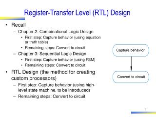
Design model: high-level block diagram • Processors & ASICs (Application-Specific Integrated Circuit) consist of 2 components: • control unit • datapath
Example: one’s counter specification • Basic algorithm: • Data = Inport • Ocount = 0 • Mask = 1 • while Data 0 repeat Temp = Data AND Mask Ocount = Ocount + Temp Data = Data >> 1 • end while • Outport = Ocount
FSM with Datapath (FSMD) • FSM: Quintuple <S,I,O,f,h> • S = Q1 x Q2 x ... x Qm • I = A1 x A2 x ... x Ak • O = Y1 x Y2 x ... x Yn • f: S x I S • h: S x I O • FSMD = FSM, extended with: • set of variables: V = V1 x V2 x ... x Vq • I = IC x ID • O = OC x OD • next state functions: • fC: S x IC x STAT S • fD: S x V x ID V • output functions: • hC: S x IC x STAT OC • hD: S x V x ID OD
State & output table Datapath Control Unit
State & output table w/ variable assignments Simpler expressions
Output = Z State-action table • This table can be used to: • construct state diagram for the control unit • synthesize next-state & output logic • define the datapath components & their connections
Algorithmic-State-Machine (ASM) chart • ASM charts: • an alternative graphic form for specifying FSMDs • may suit humans better as they explicitly show the paths from one state to another • ASM chart consists of: • state box • decision box • conditional output box • ASM block
ASM’s chart for one’s counter • One’s counter ASM chart using a standard datapath:
state-based chart input-based chart ASM’s charts for one’s counter (custom design) • The use of custom datapath may result in fewer components and interconnections. • Examples (in the case of one’s counter design): • state-based (Moore) chart requires 6 states (all variable assignments must be executed unconditionally) • input-based (Mealy) design requires 4 states (variable assignments may be executed conditionally)