Download

1 / 29
820 likes | 1.59k Views
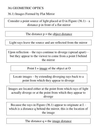
Images Formed By Lenses. Section 12.2 Pages 494 - 498. Lens Terminology. The principal axis is an imaginary line drawn through the optical centre perpendicular to both surfaces. The axis of symmetry is an imaginary vertical line drawn through the optical centre of a lens. Lens Terminology.

E N D
Images Formed By Lenses Section 12.2 Pages 494 - 498
Lens Terminology • The principal axisis an imaginary line drawn through the optical centre perpendicular to both surfaces. • The axis of symmetry is an imaginary vertical line drawn through the optical centre of a lens.
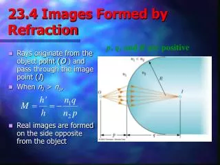
Lens Terminology • Both types of lenses have two principal focuses. • The focal point where the light either comes to a focus or appears to diverge from a focus is given the symbol F, while that on the opposite side of the lens is represented by Fʹ.
Lens Terminology • The focal length, f, is the distance from the axis of symmetry to the principal focus measured along the principal axis. • Both types of thin lenses have two equal focal lengths.
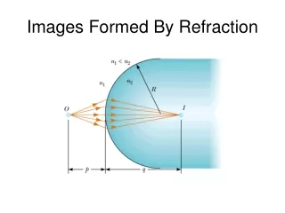
Drawing a Ray Diagram for a Lens • The light rays will bend, or refract, away from the lens surface and toward the normal. • When the light passes out of the lens at an angle, the light rays refract again, this time bending away from the normal. • The light rays undergo two refractions: • 1st on entering the lens • 2nd on leaving the lens.
When Drawing Ray Diagrams for a Lens ... Keep in mind ... • A thin lens is a lens that has a thickness that is slight compared to its focal length. An example of a thin lens is an eyeglass lens. • You can simplify drawing a ray diagram of a thin lens without affecting its accuracy by assuming that all the refraction takes place at the axis of symmetry.
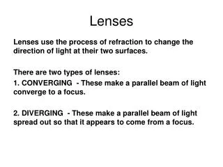
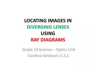
DIVERGING LENSES • A diverging lens is sometimes called a concave lens because it is thinner in the centre than at the edges. • As parallel light rays pass through a concave lens, they are refracted away from the principal axis. • The light rays spread apart (diverge) and they will never meet on the other side of the lens. • You may remember “diverging” as “dividing”.
PROPERTIES OF DIVERGING LENSES • Refracted rays appear to spread from a virtual focus called the principal focus, F. • It is on the same side as the incident rays. • The secondary principal focus, F’, is located on the other side of the lens. • Focal length (f), optical centre (O), and principal axis are the same as in a converging lens. F’ O Principal axis Focal length (f) Principal focus
Locating Images in Diverging Lens • The image rules for diverging lenses are similar to those for a converging lens. The only difference is that light rays do not actually come from the principal focus (F); they only appear to. • Follow along with Table 12.2 on page 497 of the textbook.
Locating Images in Diverging Lenses Any two of the following rays may be used to locate the image: • Draw a ray parallel to the principal axis that is refracted through the principal focus (F). • Draw a ray that passes through the secondary principal focus (F') and refracts parallel to the principal axis. • A ray that passes through the optical center goes straight through, without bending. Only two of these lines are needed to find the image.
Drawing a Diverging Lens Ray Diagram 2F’ F F’’ 2F
Ray Diagrams - Diverging Lenses • Diverging lenses always produce the same images. • Smaller, upright, virtual, and on the same side of the lens as the object. • As the object moves farther from the lens, the image becomes smaller.
CONVERGING LENSES • A converging lens is also called a convex lens because it is thicker at the centre than at the edges. • All incident parallel light rays converge at a single point after refraction. • You may remember “converging” as “concentrating”. Converging lenses are often used as magnifying glasses.
PROPERTIES OF CONVERGING LENSES • Centre of the lens is called the optical centre, O. • Refracted rays meet at a point called the principal focus, F. • It is located on the opposite side of the incident rays. • Light can strike the lens from either side, and both sides can focus parallel rays. Thus, there can be a secondary principal focus, F’, on the same side as the incident rays. F’ O Principal axis Focal length (f) Principal focus
PROPERTIES OF CONVERGING LENSES • Both F and F’ are equal distance from the optical centre. • The line through the optical centre and the two foci is called the principal axis. • The distance between F to O is the focal length, f, of the lens. F’ O Principal axis Focal length (f) Principal focus
PROPERTIES OF CONVERGING LENSES • Light can strike the lens from either side and both sides can focus parallel rays. • Thus, there can be a secondary principal focus, F’, on the same side as the incident rays. • Both F and F’ are equal distance from the optical centre. F’ O Principal axis Focal length (f) Principal focus
Drawing a Converging Lens Ray Diagram • Any ray parallel to the principal axis is refracted through the principal focus (F). • A ray that passes through the secondary principal focus (F') is refracted parallel to the principal axis. • A ray that passes through the optical center goes straight through, without being refracted (bending). As with converging mirrors, only two rays are required to locate an image. The third one acts as a check.
JIGSAW There are 5 scenarios to investigate with CONVERGING LENS. You will be placed in groups and assigned a scenario to work on, during which time you will become the ‘expert’ on that scenario. Afterwards, everyone will JIGSAW into another group where you will all have a turn to ‘teach’ your new group members about your converging lens scenario. Please reference your textbook (p.495) during this activity.
JIGSAW GROUPS GROUP 1 GROUP 2 GROUP 3 GROUP 4 GROUP 5 Adoma Julia Akin Haya Angelica Annamaria Anthony Victor Andre Alex Helder Stephanie Michael IvoCristian Vanessa Jonathan Alissia Josie Gabriel David Abdullah Higor Matthew Sevak Stephen Raffaela Rachel Victoria
2F F’ F 2F’ Object between 2F’ and F’
2F F’ F 2F’ Object beyond 2F’ (An object more than two times the distance of the focal length from the lens)
2F F’ F 2F’ Object at 2F’
2F F’ F 2F’ Object at F’ • NO IMAGE FORMED
2F F’ F 2F’ Object in front of F’