Download
1 / 15
180 likes | 435 Views
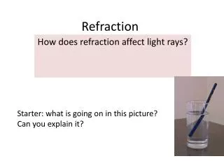
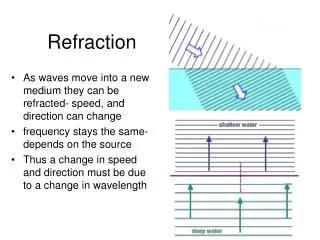
23.4 Images Formed by Refraction. p , q , and R are positive. Rays originate from the object point ( O ) and pass through the image point ( I ) When n 2 > n 1 , Real images are formed on the side opposite from the object. 23.5 Atmospheric Refraction.

E N D
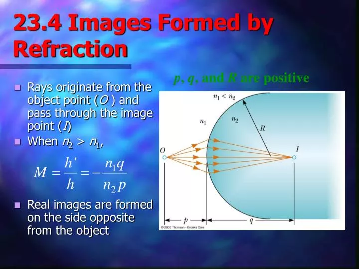
23.4 Images Formed by Refraction p, q, and R are positive • Rays originate from the object point (O ) and pass through the image point (I) • When n2 > n1, • Real images are formed on the side opposite from the object
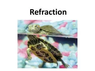
23.5 Atmospheric Refraction • There are many interesting results of refraction in the atmosphere • Sunsets • Mirages
Atmospheric Refraction and Sunsets • Light rays from the sun are bent as they pass into the atmosphere • It is a gradual bend because the light passes through layers of the atmosphere • Each layer has a slightly different index of refraction • The Sun is seen to be above the horizon even after it has fallen below it
Atmospheric Refraction and Mirages • A mirage can be observed when the air above the ground is warmer than the air at higher elevations • The rays in path B are directed toward the ground and then bent by refraction • The observer sees both an upright and an inverted image
23.6 Thin Lenses • A thin lens consists of a piece of glass or plastic, ground so that each of its two refracting surfaces is a segment of either a sphere or a plane • Lenses are commonly used to form images by refraction in optical instruments (cameras, telescopes, etc.)
Thin Lens Shapes • These are examples of converging lenses • They have positive focal lengths • They are thickest in the middle
More Thin Lens Shapes • These are examples of diverging lenses • They have negative focal lengths • They are thickest at the edges
Focal Length of Lenses • The focal length, ƒ, is the image distance that corresponds to an infinite object distance • This is the same as for mirrors • A thin lens has two focal points, corresponding to parallel rays from the left and from the right • A thin lens is one in which the thickness of the lens is negligible in comparison with the focal length
Focal Length of a Converging Lens • The parallel rays pass through the lens and converge at the focal point F • The parallel rays can come from the left or right of the lens • f is positive
Focal Length of a Diverging Lens • The parallel rays diverge after passing through the diverging lens • The focal point is the point where the rays appear to have originated • f is negative
Ray Diagrams for Thin Lenses • Ray diagrams are essential for understanding the overall image formation • Three rays are drawn • The first ray is drawn parallel to the first principle axis and then passes through (or appears to come from) one of the focal points • The second ray is drawn through the center of the lens and continues in a straight line • The third ray is drawn from the other focal point and emerges from the lens parallel to the principle axis • There are an infinite number of rays, these are the convenient ones
Ray Diagram for Converging Lens, p > f • The image is real • The image is inverted
Ray Diagram for Converging Lens, p < f • The image is virtual • The image is upright
Ray Diagram for Diverging Lens • The image is virtual • The image is upright