Download
1 / 16
180 likes | 261 Views
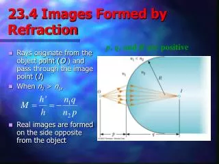
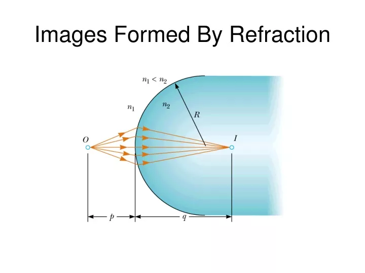
Images Formed By Refraction. Sign Conventions for Refracting Surfaces. p is positive if object is in front of surface (real object). p is negative if object is in back of surface (virtual object). q is positive if image is in back of surface (real image).

E N D
Sign Conventions for Refracting Surfaces • p is positive if object is in front of surface (real object). • p is negative if object is in back of surface (virtual object). • q is positive if image is in back of surface (real image). • q is negative if image is in front of surface (virtual image). • R is positive if center of curvature is in back of convex surface. • R is negative if center of curvature is in front of concave surface.
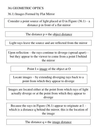
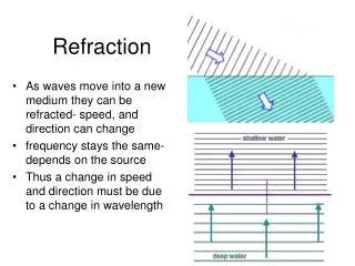
Flat Refracting Surface The image is on the same side of the surface as the object.
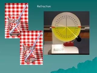
Apparent Depth The image is virtual
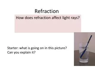
A parallel beam of light is sent through an aquarium. If a convex glass lens is held in the water, it focuses the beam 1. closer to the lens than 2. at the same position as 3. farther from the lens than outside the water.
Lens Types Converging Lenses f1: object focal point f2: image focal point Diverging Lenses
Sign Conventions for Thin Lenses • Object Distance do • do is positive if the object is in front of the lens (real object). • do is negative if the object is in back of the lens (virtual object). • Image Distance di • di is positive if the image is in back of the lens (real image). • di is negative if the image is in front of the lens (virtual image). • Image Orientation Magnification • M is positive if the image is upright with respect to the object (virtual image). • M is negative if the image is inverted with respect to the object (real image). • f is positive if the lens is converging. • f is negative if the lens is diverging.
Examples A diverging lens with f = -20 cm h = 2 cm, do = 30 cm A converging lens with f = 10 cm (a) do = 30 cm The image is real and inverted (b) do = 10 cm The image is at infinity (c) do = 5 cm The image is virtual and upright The image is virtual and upright
Ray Diagrams for a Converging Lens • Ray 1 is drawn parallel to the principal axis. After being refracted, this ray passes through the focal point on the back side of the lens. • Ray 2 is drawn through the center of the lens and continues in a straight line. • Ray 3 is drawn through the focal point on the front side of the lens (or as if coming from the focal point if p < f) and emerges from the lens parallel to the principal axis.
The image is real and inverted The image is virtual and upright
Ray Diagrams for a Diverging Lens • Ray 1 is drawn parallel to the principal axis. After being refracted, this ray emerges such that it appears to have passed through the focal point on the front side of the lens. • Ray 2 is drawn through the center of the lens and continues in a straight line. • Ray 3 is drawn toward the focal point on the back side of the lens and emerges from the lens parallel to the principal axis.
I1 O I2 f2 f1 Combination of Thin Lenses • First find the image created by the first lens as if the second lens is not present. • Then draw the ray diagram for the second lens with the image from the first lens as the object. • The second image formed is the final image of the system.
Java Applet for Lens and Mirrors • http://www.phy.ntnu.edu.tw/java/index.html