Download
1 / 37
380 likes | 673 Views
Flexible Microplasma Devices: Phototherapeutic Bandages. Senior Design Final Presentation December 1 st , 2005 Kate Tobin and Jason Readle, Group 13 TA: Alexander Spektor. Outline. Introduction Objectives Original Design Fabrication Challenges and Design Decisions Testing Performance

E N D
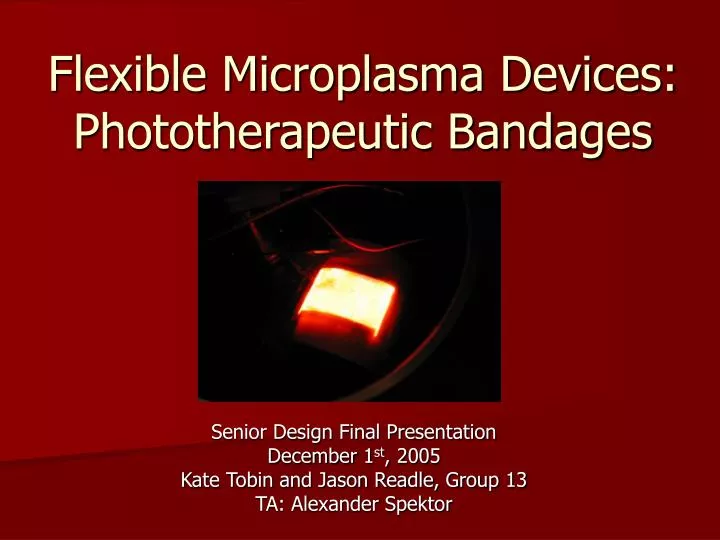
Flexible Microplasma Devices: Phototherapeutic Bandages Senior Design Final Presentation December 1st, 2005 Kate Tobin and Jason Readle, Group 13 TA: Alexander Spektor
Outline • Introduction • Objectives • Original Design • Fabrication • Challenges and Design Decisions • Testing • Performance • Safety • Recommendations
Introduction • Devices consist of two treated flexible aluminum strips • Plasma forms in the gap between strips and cavities • Gas selection determines output spectrum • Flexible light-emitting devices such as these have many potential medical applications
Objectives • Fabricate devices to operate in vacuum chamber • Also develop a packaging to allow the devices to work outside the chamber • Test and characterize device performance • Evaluate safety of device for medical use
Wavelengths for Phototherapy • Irradiation devices with output from 400-500nm have been effective against eczema[1] • UVA (340-400nm) has been successfully used to treat sclerosing skin diseases[2] • A wide range of wavelengths have been used in tandem with photosensitizers for photodynamic therapy, with many new sensitizers with strong absorbance at 650-850nm [3],[4] • Time interval between sensitizer administration and light treatment can often be several days[3] • Dosage required varies, 3 J/cm2 – 500 J/cm2 [4] • J. Krutmann, K. Medve-Koenigs, T. Ruzicka, U. Ranft, J. H. Wilkens, “Ultraviolet-free phototherapy,” Photodermatology Photoimmunology Photomedicine, vol. 21, pp. 59-61, 2005 • M. Brenner, T. Herzinger, C. Berking, G. Plewig, K. Degitz, “Phototherapy and photochemotherapy of sclerosing skin diseases,” Photodermatology Photoimmunology Photomedicine, vol. 21, pp. 157-165, 2005 • D. Dolmans, D. Fukumura, R. K. Jain, “Photodynamic therapy for cancer,” Nature Reviews Cancer, vol. 3, pp. 380-387, 2003 • 4 T. J. Dougherty, C. J. Gomer, B. W. Henderson, G. Jori, D. Kessel, M. Korbelik, J. Moan, Q. Peng, “Photodynamic therapy: review,” Journal of the National Cancer Institute, vol. 90, pp. 889-905, 1998
Photodynamic Cancer Treatment D. Dolmans, D. Fukumura, R. K. Jain, Photodynamic therapy for cancer,” Nature Reviews Cancer, vol. 3, pp. 380-387, 2003
Original Design (Proprietary information deleted)
Original Design • Al2O3 as dielectric barrier on strips • Acts as barrier to sputtering caused by AC plasma • Protect against shorting out/breakdown • Supports electric field to excite gas • Glass paste to enhance durability and dielectric strength
Fabrication Untreated Sample Anodization Glass Paste Baking
Vacuum Chamber Devices Wire Attachment Polyimide Tape Vacuum Chamber Device Vacuum Chamber Device
Packaged Devices (Proprietary information deleted)
Challenges and Design Decisions • Thickness of Al2O3 layer • Too thick: higher operating voltages • Too thin: risk of breakdown greater • First vacuum chamber device may have experienced breakdown due to thinner layer • Glass paste consistency • Protects devices from wrinkling easily and increases dielectric strength, but can make device stiff if too thick
Challenges and Design Decisions • Gas selection • He, Ne, and N2 all have emission lines favorable to certain medical applications • He has much lower intensity, difficult to generate N2 plasma without raising voltage too high • Focused testing on Ne • Lengthy fabrication process • Out of 35+ strips cut, only 3 devices (6 strips) survived for demonstration (2 vacuum chamber devices, 1 packaged device)
Challenges and Design Decisions (Proprietary information deleted)
Tests Performed • L-I (chamber only) and I-V by adjusting supply voltage and measuring output light (cd/m2) and supply current, derived resistance and efficiency from this • Output spectrum and uniformity using CCD camera • Tested leakage in packaged device using pressure transducer • Measured temperature and conductivity of packaged device with thermocouple and multimeter
L-I-V, Flat Device Turn on
L-I-V, Bent Device Turn on
I-V, Packaged Device (Proprietary information deleted)
Measured Luminance (cd/m^2) at 9 points on Flat Device with constant voltage and pressure, during best operation we could achieve Uniformity As a reference, commercial flat lamp for backlighting has non-uniformity of ~ 20%
Differential Resistance Most plasma devices have negative differential resistance
706 nm 390 nm 427 nm
585 nm 702 nm
Packaging Test (Proprietary information deleted)
Resistance of Packaging • Multimeter was unable to read anything but “open” during testing, and is rated to go up to 20 MΩ • Only discharge array would be exposed in final product
Operating Temperature • After device had been running 30 minutes, temperature stabilized at 38 °C (100 °F) • Negative temperature effects do not begin until 43 °C (restricted blood flow) • Packaging was exposed to up to 80 °C over the course of an hour without comprising its integrity
Range of Operating Voltages • Wide operating range turn-on voltage and breakdown • Table corresponds to tests with Neon at 700 T • This will permit the use of a fixed-voltage power supply, i.e. 230 Vrms, so that users cannot harm themselves adjusting voltage
Recommendations • Automated and standardized fabrication process to improve device uniformity • Improved uniformity would allow for higher applied voltages • Greater output intensity without breakdown • Use of more difficult gases such as N2 • Bulk production – roll to roll process (to reduce costs) • Sealing packaging in desired gas environment • (Proprietary information deleted)
Thanks • Dr. Sung-Jin Park – Visiting Professor, Mentor • Alex Spektor – ECE 445 T.A. • Dr. J. Gary Eden – Director of Laboratory for Optical Physics and Engineering • Kwang Soo Kim – Graduate Student