Download
1 / 81
920 likes | 1.4k Views
Secondary Storage Devices. Chapter 3. Secondary Storage Devices. Logical vs. Physical Devices Rather then require user software to "know" about specific device types and names, "logical" device names are used to hide device specifics

E N D
Secondary Storage Devices Chapter 3
Secondary Storage Devices • Logical vs. Physical Devices • Rather then require user software to "know" about specific device types and names, "logical" device names are used to hide device specifics • If device changes (system changed or program moved to new system), user must simply assign new device physical name appropriate logical name.
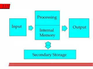
Secondary device types • Magnetic disk • Magnetic tape • Semiconductor memory devices • Mass storage devices
Magnetic disks • Disk platters, coated with ferrous oxide, rotate on a spindle. • Read/write heads read and record information in single bit wide "tracks". • These tracks are broken up into blocks, or "sectors".
Magnetic disks • Performance - 3 aspects to timing • seek time - time to move head to the correct cylinder. • Latency - time for disk to rotate to correct position. • Transfer rate - speed at which data may be read. • Instantaneous - rate at an instance in time • Average - rate including time for IBG
Magnetic disks • Hard disks. • Sector - block size on disk (if fixed). • Track - all sectors in a concentric circle. • Platter - one physical disk - two surfaces. • May have multiple platters. All parallel tracks form a "cylinder".
Magnetic disks • Disks spin fast (~ 3600 rpm). • Heads "fly" over surface. • If they touch, or "crash" both heads and surface may be damaged. • the closer the heads, the higher the density • Movable heads must accurately locate correct track. • Often one surface is used for timing and position sensing
Magnetic disks • Fixed Winchester technology disks • since sealed, no dirt can cause crash, heads fly very close. • May have multiple heads per surface. • High density. • Fast (mult. heads & high dens.)
Magnetic disks • Removable • Lower density then fixed.
Magnetic disks • Fixed head • One head for every track. • Very fast. • Expensive
Magnetic disks • Floppy disks: • single flexible platter • Rotate slowly (360 rpm) • Head in constant contact with surface • Easily damaged • Heads seek slowly
Magnetic disks • Disk defects • due to the thinness of the surface coating, most disks have small flaws or defects • Spare tracks or sectors are provided for storage of data that normally would be stored in the damaged location. • Either the hardware or software must handle these "bad" sections.
Magnetic disks • Disk track formats • Tracks are divided into either fixed length sectors or variable or user-defined length blocks.
Sector-addressable devices • The disk tracks are subdivided into fixed size sectors. • Advantages: • simple allocation of storage space • simple address calculations • Disadvantages • Internal fragmentation 12 13 1 2 11 3 10 4 9 5 8 7 6
Sector-addressable devices - interleaved • Disks spin too fast too fast to read adjacent blocks • Solution - interleave blocks • Logically adjacent blocks not physically adjacent • Interleaving facter - distance between blocks 9 5 1 10 13 6 Interleave Factor: 3 4 2 8 11 12 3 7
Sector-addressable devices - interleaved • If the factor is n, the n revolutions are required to read the whole track • High performace controller speeds now allow up to 1:1 interleaving! 9 5 1 10 13 6 Interleave Factor: 3 4 2 8 11 12 3 7
Sector-addressable devices - Clustered • File System groups sectors into logically contiguous clusters. • All allocation, reading, and writting is done on an entire cluster. • For Example, with 512 byte sectors, can have cluster sized ranging from 1 to 65,535 sectors.
Sector-addressable devices - Clustered • Advantages over non-clustered • Blocking - do less reads and writes, to faster overall performance • Management - maintain information on file as a list of clusters, rather then a (longer) list of sectors File allocation table cluster cluster number location 1 • 2 • 3 • ... 1 2 3
Sector-addressable devices - Clustered • Disadvantages • More Wasted Space - more Internal Fragmentation • Thus cluster size is a space/time tradeoff!
Sector-addressable devices - extents • An extent is a physically contiguouus collection of clusters • If a file is in one extent, it is all physically continguious. • Reduces seek time to read entire file • A file may need more then one extent if not enough physical contiguous available • the disk is “fragmented”
Block-addressable devices • Block size is programmable, as in magnetic tapes. • Blocks sizes may be mixed on a single device. • Advantages: • As with mag. tape, space is saved by blocking (fewer gaps) as a multiple of logical record size • no internal fragmentation! (unused area at end of block) • Disadvantages • External Fragmentstion • Complex space management
Space utilization • Space utilization of sector addressable devices • Consider a disk with: • 512 bytes per sector • 32 sectors per track • 20 track per cylinder • 400 cylinders/disk pack • what is the disk size in bytes? • 512 * 32 * 20 * 400 = 131,072,000 bytes • or 131 megabytes.
Space utilization • How many sectors will be used to store 8,000 records on the above disk if record size is 100 bytes? • Blocking factor = 5 Thus
Space utilization • Utilization - how much is used? • Thus:
Nondata Overhead • Disk require space for nondata overhead • interblock gaps • block headers • synchronization marks • These fields are invisible on sector addressable devices, and usually need not be considered in space computations.
Magnetic Disk Timing • Timing is a function of the following device specific factors: • Seek time • rotational delay (latency) • transmission time (read time) • The times for these is not fixed, but vary based on the previous status of the disk drive, disk and head position relative to desired position.
Magnetic Disk Timing • Consider the following times: • Seek time: • Track to track time: 1 milliseconds • Full disk movement: 9 milliseconds • average move time: 7.6 milliseconds • Rotational Speed: 7200 RPM • Average rotational delay: (60/7200)/2 = 4.16 milliseconds • Transfer rate: 66.6 Mbytes/second • Sector size: 512 bytes
Magnetic Disk Timing • Thus is would take:to transfer a sector.
Magnetic Disk Timing • Average access per sector is:average sector access time = seek time + • rotational delay + • transfer time • Thus, for the case above: • average sector access time is 7.6 + 4.16 + .00776 = 11.76776 ms
Magnetic tape • Typically nine tracks wide • 800, 1600, 6250 bits per inch (bpi) • Storage based on the magnetic polarity of ferrous oxide particles on the tape. • The tape moves over read/write heads to store and retrieve information
Magnetic tape • The write head magnetizes small regions of the tape in one of two directions. • The read head senses the places where magnetic polarity changes, called "flux change". • Flux changes cause an electrical current to be produced in the windings of the read head. • Speed varies between 40 to 200 inches per second (ips)
Magnetic tape • Vacuum loops hold a reservoir of tape. • This way the bulky reels do not have to keep up with acceleration/deceleration of tape, but can catch up a short time later.
Magnetic tape • Streaming tape drive - No loops needed. • Very slow in start/stop mode (~20k/sec), but extremely fast in continuous mode. (~160k/sec). • Often these are cartridge type devices. • Used for high speed/low cost backup devices.
Magnetic tape • Error checking and correction • Even/odd parity. • Vertical redundancy checking (VCR): An extra bit per column is set or clear to make the number of bits set either even or odd. • Longitudinal redundancy checking (LCR): Each "row" of bits in a block has a parity bit. • Using VCR and LCR together, errors may be found and corrected in flight.
Magnetic tape • Error checking and correction • Checksum • addition of all data in a block together using modulo arithmetic. • Then this values is recorded at the end of the data block.
Magnetic tape • Error checking and correction • Cyclic redundancy check (CRC) • Based on calculating polynomial functions of data. • Can correct multiple errors.
Magnetic tape • Error checking and correction • Soft error - errors which can be corrected • Hard errors, errors that can not be corrected.
Magnetic tape • Blocking • Tapes must be read at a constant speed. • To facilitate starting and stopping midtape, interblock gaps (IBG) are used to allow time for acceleration/ deceleration of tape. • Typical size 0.6 inch. IBG
Magnetic tape • Buffering • Blocks of tape read into buffer for subsequent processing. • One physical block may hold several logical blocks. • blocking factor - number of logical blocks per physical block. • Optimizes slow I/O time.
Space utilization • Blocking factor greatly affects utilization of tape. • Block size = record size x blocking factor • gap length = density (bytes per inch) x gap length (in)
Space utilization • Consider: • 6250 BPI tape • 0.6 inch IBG • 100 byte records
Timing considerations • Consider • 6250 BPI tape • 100 byte records • 100 IPS (inches per second) • .03 second start time • .03 second stop time
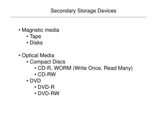
CR-ROM • 600 megabytes • read-only (write-once) • very cheap to produce • History: • Offspring of videodisk from late 60’s, early 70’s. Many standards caused problems. • Early 80’s work began on developing a audio disc’s • Sony and Philips developed as a standard. • Introduced in 1984 • File system standard developed in 1985. • DVD is the latest in CD standards - 10 gigabytes
CR-ROM • Strengths • High Capacity • Inexpensive • Durable • Weaknesses • extremely slow seek speed (transfer rate in reasonable)
CR-ROM: Physical Organization • Creating • Bits stored as Pits and Lands: • CD-ROMs are stamped from a glass master disk which has a coating that is changed by the laser beam. • When the coating is developed, the areas hit by the laser beam turn into pits along the track followed by the beam. • The smooth unchanged areas between the pits are called lands.
CR-ROM: Physical Organization • Reading • A beam of laser light is focused on the track as it moves under the optical pickup. • The pits scatter the light, but the lands reflect most of it back to the pickup. • This alternating pattern of high- and low-intensity reflected light is the signal used to reconstruct the original digital information.
CR-ROM: Physical Organization • Digital Encoding • 1’s are represented by the transition from pit to land and back again. • 0’s are represented by the amount of time between transitions. • The longer between transitions, the more 0’s we have.