Download
1 / 49
490 likes | 680 Views
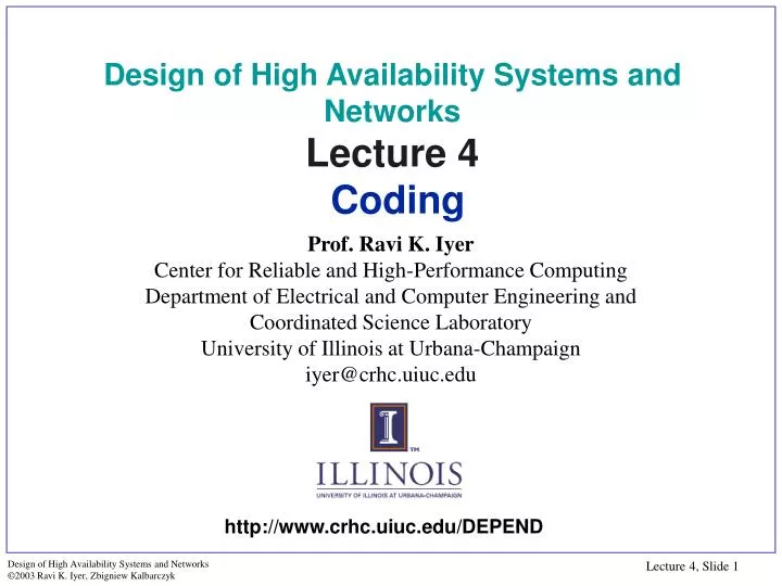
Design of High Availability Systems and Networks Lecture 4 Coding. Prof. Ravi K. Iyer Center for Reliable and High-Performance Computing Department of Electrical and Computer Engineering and Coordinated Science Laboratory University of Illinois at Urbana-Champaign iyer@crhc.uiuc.edu.

E N D
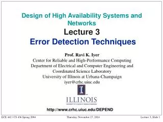
Design of High Availability Systems and NetworksLecture 4 Coding Prof. Ravi K. Iyer Center for Reliable and High-Performance Computing Department of Electrical and Computer Engineering and Coordinated Science Laboratory University of Illinois at Urbana-Champaign iyer@crhc.uiuc.edu http://www.crhc.uiuc.edu/DEPEND
Outline • Error detecting and error correcting codes • Codes for storage and communication • Codes for arithmetic operations • Codes for control units • Example application: • Design of a failure resilient node/network controller
Fault Detection through Encoding • At logic level, codes provide means of masking or detection of errors • Formally, code is a subset S of universe U of possible vectors • A noncode word is a vector in set U-S U = 28 vectors X1 is a codeword <10010011> Due to multiple bit error, becomes X3 = <10011100> not detectable X2 is a codeword, becomes X4 noncode detectable S = even parity X1 X2 X3 X4
Basic Code Operations • Consider n-bit vectors, space of 2n vectors • A subset of 2n vectors are code words • Subset called (n, k) code, where fraction k/n is called rate of code • Addition operation on vectors is bit-wise exclusive-OR X + Y = < x1 y1, x2 y2, …, xnyn > • Multiplication operation is bitwise AND cX = < cx1, cx2, …, cxn >
Basic Concepts & Hamming Distance • Code, codeword, encoding, decodingerror detection code, error correcting code • Hamming distance properties: • The Hamming weight of a vector x (e.g., codeword), w(x), is number of nonzero elements of x. • Hamming distance between two vectors x and y, d(x,y) is number of bits in which they differ. • Distance of a code is a minimum of Hamming distances between all pairs of code words. Example: x = (1011), y = (0110) w(x) = 3, w(y) = 2, d(x, y) = 3
Distance Properties • To detectall error patterns of Hamming distance d,codedistance must be d+1 • e.g., code with distance 2 can detect patterns with distance 1 (i.e., single bit errors) • To correct all error patterns of Hamming distance c, code distance must be 2c + 1 • To detectall patterns of Hamming distance d, and correct all patterns of Hamming distance c, code distance must be 2c + d + 1 • e.g., code with distance 3 can detect and correct all single-bit errors,
Odd and even parity codes for BCD data Decimal Digit BCD BCD odd parity BCD even parity 0 1 2 3 4 5 6 7 8 9 0000 0001 0010 0011 0100 0101 0110 0111 1000 1001 00001 00010 00100 00111 01000 01011 01101 01110 10000 10011 00000 00011 00101 00110 01001 01010 01100 01111 10001 10010 Parity Parity Bit Parity Checking Error Signal Parity Generator Data Parity Bit Parity Bit Data Memory ~ ~ ~ ~ Data In Data Out Parity Codes - Example Organization of a memory that uses single-bit parity. The parity bit is generated when data is written to memory and checked when data is ready.
XOR Tree for Parity Generation Data Bits d0 d1 d2 Generated Parity Bit d3 Error Signal P
P 15 14 13 12 11 10 9 8 7 6 5 4 3 2 1 0 15 14 13 12 11 10 9 8 7 6 5 4 3 2 1 0 P2 P1 Chip 1 Chip 2 Chip 3 Chip 5 Chip 4 P4 P3 P2 P1 7 6 5 4 3 2 1 0 11 10 9 8 15 14 13 12 Chip 3 Chip 2 Chip 5 Chip 4 Chip 1 P4 P3 P2 P1 7 6 5 4 3 2 1 0 11 10 9 8 15 14 13 12 P4 P3 P2 P1 15 14 13 12 11 10 9 8 7 6 5 4 3 2 1 0 Codes for RAMs Odd or Even Bit-per-word parity Bit-per-byte parity Even Odd Bit-per-multiple-chips parity Bit-per-chip parity Interlaced parity
Parity Prediction in Arithmetic Circuits • Binary adder • Two inputs: a = (an-1 … a0 ac) and b = (bn-1 … b0 bc) • Two operands to be added: (an-1 … a0) and (bn-1 … b0) • ac and bc are check bits of a and b respectively • Encoded output will be s = (sn-1 … s0 sc) where (sn-1 … s0) are determined by the ordinary binary addition of (an-1 … a0) to (bn-1 … b0) and sc is the check bit for (sn-1 … s0) • Then • Reduces to
an-1 a0 ac bn-1 b0 bc Binary adder c0 ... cn-1 ... ... + sn-1 s0 Error Parity Prediction in Binary Adder
s0 a1 s1 sn-1 b1 a0 b0 Sum Sum c0 c1 c2 Carry Carry Carry Carry Error + ... s1 s0 sn-1 Parity-Checked Binary Adder an-1 bn-1 Sum ... ... cn-1 ... ac bc (a)
Carry look-ahead circuit sn-1 cn-1 s1 s0 Sum c0 Sum Sum a1 a0 ... a n 1 b1 b0 b n 1 c1 Carry Carry c2 Error ... + ac s1 s0 bc sn-1 (b) Parity-Checked Binary Adder (cont.)
Binary Multiplier Therefore, denoting the check bit for (p7 …p0) by pc
c s c s c s a3 a2 a0 Multiplier Using Array of Full-Half Adders a0 a1 a3 a2 b0 HA: Half Adder FA: Full Adder S: Sum C: Carry a0 a1 a3 a2 b1 HA HA HA C3 , 1 C 2 , 1 C1 , 1 a0 a1 b2 FA FA FA c s c s c s C 2, 2 C 1, 2 a1 a3 a2 C 3, 2 b3 FA FA FA c s c s c s C 2 , 3 C 1 , 3 C 3, 3 FA FA HA c s c s c s C 3, 4 C 2, 4 C 1 , 4 p6 p0 p5 p4 p5 p2 p1 p7
Four information bits Three parity bits 3 2 1 0 P2 P1 P0 Bit in error Parity in error 3 P2 P1 P0 2 P2 P1 1 P2 P0 0 P1 P0 P2 P2 P1 P1 P0 P0 Overlapping Parity • Parity groups are formed with each bit appearing in more than one parity group • Errors can be detected and located • Erroneous bit can be corrected by a simple complementation
P1 P2 P0 1 3 2 0 2 0 3 1 3 0 1 2 3 Parity Generator Parity Generator Parity Generator V V V Pr1 Pr0 Pr2 C 0 Correct Bit 0 Pr0 C 1 Correct Bit 1 P0 C 2 Correct Bit 2 C 3 3-8 Decode Pr1 Correct Bit 3 CP 0 Correct Bit P0 P1 CP 1 Correct Bit P1 CP 2 Pr2 Correct Bit P2 E P2 No Error C 0 B it 0 B it 0 C 1 B it 1 B it 1 Corrected Bits C 2 B it 2 B it 2 CP 2 B it P2 B it P2 Error Correction with Overlapped Parity
Require from 10% to 40% redundancy Best thought of as overlapping parity The Hamming single-error correcting code uses c parity check bits to protect k bits of information: 2c c + k + 1 Example: suppose four information bits (d3, d2, d1, d0) and as a result three parity bits (p1, p2, p3) the bits are partitioned into groups as (d3, d1, d0, p1), (d3, d2, d0, p2) and (d3, d2, d1, p3) the grouping of bits can be determine from a list of binary numbers from 0 to 2k - 1. each check bit is specified to set the parity, either even or odd, of its respective group 1 2 3 4 5 6 7 Hamming Error-Correcting Code Determining the bit groups ( three parity bits) 0 0 0 0 0 1 1 0 1 0 2 0 1 1 3 3 1 0 0 4 1 0 1 5 5 1 1 0 6 6 1 1 1 7 7 7 Parity bits calculation p1 = XOR of bits (3, 5, 7) p2 = XOR of bits (3, 6, 7) p3 = XOR of bits (5, 6, 7) Parity checking c1 = XOR of bits (1,3, 5, 7) c2 = XOR of bits (2,3, 6, 7) c3 = XOR of bits (4,5, 6, 7) Observe that each group of bits for parity checking starts with a number that is a power of 2, e.g., 1, 2, 4. p1 p2 d0 p3 d1 d2 d3
Check Bits and Syndromes for Single-Bit Errors • The original data is encoded by generating a set Cg, of parity bits. • To check correctness, the encoding process is repeated and a set Cc, of parity bits is generated. • If Cg and Cc agree, the information is correct. • If Cg and Cc disagree, the information is incorrect and must be corrected. • To aid the correction, a syndrome is defined: The syndrome is a binary word that has 1 in each bit position in which Cg and Cc disagree; the syndrome points directly to the erroneous bit. Erroneous bits Check bits affected Syndromes d0 p1, p2 110 d1 p1, p3 101 d2 p2, p3 011 d3 p1, p2, p3 111 p1 p1 100 p2 p2 010 p3 p3 001
d1 d3 d3 d0 d2 d1 d2 d3 d0 p1 p2 C1 C2 d0 p1 p2 d2 d1 p3 d3 Controlled Complementation Unit d2 d3 p2 p3 d0 p1 d1 Hamming Single-Error Correction Unit 1 2 3 4 5 6 7 Hamming single-error correction unit for four information bits and three check bits p1 p2 d0 p3 d1 d2 d3 Parity Generator Parity Generator Parity Generator p1 p3 * p2 * * p3 C3 Syndrome C1 Syndrome determines which bit (if any) Is complemented Syndrome C2 C3 Corrected Bits
Hamming Single-Error Correction Unit 1010 A B 1 C 010 1 0 1 1 010 Error 1011011 A=1, B=1, C=1 Syndrome= 111 Complementando: 1010 A B 1 C 010 1 0 1 1 010 Error 10010100010 A=0, B=1, C=1 Syndrome= 110 Complementando:
d2 d3 p4 p3 d1 p1 p2 d0 1 1 1 1 1 1 1 1 c4 c1 0 0 1 1 1 0 0 1 c2 0 1 1 0 0 1 1 0 c3 1 1 1 0 1 0 0 0 Single Error Correction and Double Error Detection Hamming Code (SEC-DED) • Consider a data word consisting of four information bits • Three parity bits are needed to provide single error correction • Adding an extra parity bit, the Hamming code can be used to correct single bit errors and to detect double errors Check bits computation P1 = XOR (3, 5, 7) P2 = XOR (3, 6, 7) P3 = XOR (5, 6, 7) P4 = parity over the first 7 bits of the code word c1 c2 c3 c4 No errors Single error in a position (x1x2x3) Double error Error in bit p4 0 0 0 0 1 x2 x3 x1 Syndromes computation C1 = XOR (1, 3, 5, 7) C2 = XOR (2, 3, 6, 7) C3 = XOR (4, 5, 6, 7) C4 = parity over all 8 bits of the code word y2 y3 0 y1 0 0 1 0
c1 c2 c3 c4 No errors Single error in position 3 Single error in position 6 Double error Error in bit p4 1 0 0 0 0 1 1 1 0 2 3 1 0 1 1 4 0 0 0 1 0 0 1 0 5 Single Error Correction and Double Error Detection Hamming Code (SEC-DED) Example Initial data d0 d1 d2 d3 0 1 1 0 d2 d3 p4 p3 d1 p1 p2 d0 1 1 0 1 0 0 0 1 1 2 0 0 0 1 1 1 1 1 Failurescenarios 3 1 1 0 0 1 0 0 0 4 1 0 0 0 0 0 1 0 1 1 0 5 1 1 1 0 0 Corresponding Syndromes
Codes for Storage and Communication Cyclic Codes • Cyclic codes are parity check codes with additional property that cyclic shift of codeword is also a codeword • if (Cn-1, Cn-2 ... C1, C0) is a codeword, (Cn-2, Cn-3, ... C0, Cn-1) is also a codeword • Cyclic codes are used in • sequential storage devices, e.g. tapes, disks, and data links • communication applications • An (n,k) cyclic code can detect single bit errors, multiple adjacent bit errors affecting fewer than (n-k) bits, and burst transient errors • Cyclic codes require less hardware, in form of linear feedback shift registers • parity check codes require complex encoding, decoding circuit using arrays of EX-OR gates, AND gates, etc.
Cyclic Code and Polynomials • Cyclic codes depend on the representation of data by a polynomial • If (Cn-1, Cn-2 ... C1, C0) is a codeword, its polynomial representation is C(x)= Cn-1 xn-1 + Cn-2xn-2 + ... C1x + C0 • Cyclic codes are characterized by their generator polynomial g(x) • g(x) is a polynomial of degree (n-k) for an (n,k) code, with a unity coefficient in (n-k) term • g(x) is a factor of xn-1, i.e., it divides it with zero remainder • if a polynomial with degree n-k divides xn-1, then g(x) generates a cyclic code • Example: for (7,4) code, g(x) = x3 + x + 1
x7+ x6 + x5 + x3 Multiplication (x4 + x3 + x2 + 1)(x3 + x) + x5 + x4 +x3 +x = x7 + x6 + x4 + x Division Quotient x x4 + x3 + x2 + 1 x5 + x4 x5 + x4 + x3 + x x3 + x Remainder Basic Operations on Polynomials • Can multiply or divide one polynomial by another, follow modulo 2 arithmetic, coefficients are 1 or 0, and addition and subtraction are same
Cyclic Code - Example • Consider generator polynomial g(x) =x3 + x + 1 for (7,4) code • Can verify g(x) divides x7 -1 • Given data word (1111), generate codeword • d(x) =x3 + x2 + x + 1 • Then c(x) = g(x)d(x) = (x3 + x2 + x + 1) (x3 + x + 1) = x6 + x5 + x3 + 1 • Hence code word is (1101001)
v(x) x x x g(x)=x3 + x + 1 d(x) + + clock v(x) + + Reg 1 Reg 2 Reg 3 d(x) Circuit to Generate Cyclic Code Consider blocks labeled X as multipliers, and addition elements as modulo 2 Another representation is to replace multipliers by storage elements, adders by EX-OR gates
Cyclic codes for 4-bit information words. Information (d0, d1, d2, d3,) Code (0,1,2,3,4,5 ,6) 0000 0001 0010 0011 0100 0101 0110 0111 1000 1001 1010 1011 1100 1101 1110 1111 0000000 0001101 0011010 0010111 0110100 0111001 0101110 0100011 1101000 1100101 1110010 1111111 1011100 1010001 1000110 1001011 clock v(x) + + Reg 1 Reg 2 Reg 3 d(x) The encoding process Register values 0 1 2 3 4 5 6 7 1 0 1 1 0 1 0 0 0 2 0 0 1 1 0 1 0 0 3 0 1 1 1 0 0 1 0 Clock period D(x) V(x) 1 1 0 1 0 0 0 1 0 1 0 0 0 1 Data polynomial = d0 + d1x + d2x2 + d3x3 Generator polynomial = 1 + x + x3 Code polynomial = 0 + 1x + 2x2 + 3x3 + 4x4 + 5x5 + 6x6 Generation of Code Words
Decoding of Cyclic Codes • Determine if code word (rn-1, rn-2, ....., r1, r0) is valid • Code polynomial r(x) = rn-1 xn-1 + rn-2 xn-2 + ... r1 x+ r0 • If r(x) is a valid code polynomial, it should be a multiple generator polynomial g(x) • r(x) = d(x) g(x) + s(x), where s(x)the syndrome polynomial should be zero • Hence, divide r(x) by g(x) and check the remainder whether equal to 0
b(x) = (x3 + x) d(x) v(x) + b(x) = d(x) v(x) = (x3 + x + 1) d(x) Hence, d(x) = v(x) / (x3 + x + 1) v(x) = d(x) - b(x) = d(x) - (x3 + x) d(x) = (x3 + x +1)dx b(x) v(x) + + d(x) x x x + + Circuits for Decoding Another representation is to replace multipliers by storage elements and adders by EX-OR gates v(x) Reg 1 Reg 2 Reg 3 d(x) Note: Once the division is completed, the registers contain the value of the syndrome (remainder) clock
v(x) + + Generator polynomial, g(x) = x3 + x +1 Reg 1 Reg 2 Reg 3 d(x) clock Example Decoding The decoding process with correct information The decoding process with erroneous information Register values Register values 0 1 2 3 4 5 6 7 1 0 0 0 1 1 0 1 0 2 0 0 1 1 0 1 0 0 3 0 1 1 0 1 0 0 0 0 1 2 3 4 5 6 7 1 0 0 0 1 1 0 0 1 2 0 0 1 1 0 0 1 1 3 0 1 1 0 0 1 1 0 Clock period V(x) B(x) D(x) Clock period V(x) B(x) D(x) 1 0 1 0 0 0 1 0 1 1 1 0 0 1 1 1 0 1 0 0 0 1 0 1 1 0 0 1 0 1 1 1 1 1 1 1 1 0 0 1 1 0 Received word Code word Original Information Nonzero Syndrome Syndrome
Systematic Cyclic Codes • Previous cyclic codes were not systematic, i.e. data not part of code word • To generate (n,k) systematic cyclic code, do the following: • Multiply d(x) by xn-k, this is accomplished by shifting d(x) n-k bits • The code polynomial is c(x) = r(x) + xn-k d(x) with r(x) =Rem[xn-k d(x) :g(x)] • Hence xn-k d(x) + r(x) = g(x)q(x), which is code word c(x) since it is a multiple of g(x)
Systematic (7, 3) Cyclic Code Generated by G(x) = x4 +x3+x2+1 Message Bits Code Word x4M(x) - C(x) m2 m1m0 x4M(x) C(x) = Rem[x4M(x) G(x)] 6543210 000 001 010 011 100 101 110 111 0 x4 x5 x5+x4 x6 x6+x4 x6+x5 x6+x5+x4 0 x3+x2+1 x2+x+1 x3+x x3+x2+x x+1 x3+1 x2 0000000 0011101 0100111 0111010 1001110 1010011 1101001 1110100 d(x) x n-k Example of Systematic Cyclic Code • Generator polynomial g(x) = x4 + x3 + x2 + 1 of (7,3) code • Data is 3 bits, n-k = 4 bits
dn rn Transfer d5 r5 d4 r4 d3 r3 d2 r2 Checksum on Received Data d1 r1 Compare di = original word of data ri = received word of data Received Version of Checksum Checksum on Original Data Checksum Codes - Basic Concepts • The checksum is appended to block data when such blocks are transferred
} 0 1 1 1 0 0 0 1 0 1 1 0 1 0 0 0 Original Data Checksum (Addition) + ( ) 0 1 1 0 1 Original Data Original Data d0 d1 d3 d2 d1 d0 d3 d2 d1 d0 d2 d3 0 1 1 1 1 1 1 1 Faulty Line Always “1” 0 0 0 1 1 0 0 1 Transmit Receive 0 1 1 0 1 1 1 0 Received Checksum 0 0 0 0 1 0 0 0 Checksum Checksum of Received Data 1 1 1 0 1 1 1 0 1 1 1 0 Single Precision Checksums Carry is Ignored A single-precision checksum is formed by adding the data words and ignoring any overflow The single-precision checksum is unable to detect certain types of errors. The received checksum and the checksum of the received data are equal, so no error is detected.
Original Data Received Data d3 d2 d1 d0 d3 d2 d1 d0 0 1 1 1 1 1 1 1 d0 d1 0 0 0 1 1 0 0 1 d2 d3 0 1 1 0 1 1 1 0 0 0 0 0 1 0 0 0 Faulty Line Always “1” Checksum Checksum of Received Data Transmit Receive 0 0 0 0 1 1 1 0 Received Checksum 0 0 1 0 1 1 1 0 1 0 0 0 1 1 1 0 Double Precision Checksums Compute 2n-bit checksum for a block of n-bit words Overflow is still a concern, but it is now overflow from a 2n-bits The received checksum and the checksum of the received data are not equal, so the error is detected
Original Data Word n d3 d2 d1 d0 Received Data d0 0 1 1 1 d1 d3 d2 d1 d0 Word 3 0 0 0 1 d2 Transmit Receive Word 2 d3 1 1 1 1 0 1 1 0 Word 1 Word n - 1 Word n 1 0 0 1 0 0 0 0 Faulty Line Always “1” 1 1 1 0 Word 9 Word 10 1 0 0 0 0 0 0 1 0 1 1 1 Word 7 Word 8 0 0 0 0 0 1 1 0 Word 5 Word 6 1 0 0 1 1 1 1 1 Word 3 Word 4 Checksum of Original Data Checksum of Received Data 1 0 0 0 1 1 1 0 Word 1 Word 2 10 0 1 0 0 0 1 1 1 0 1 1 1 0 1 Received Checksum Checksum 0 0 1 0 1 1 0 1 Honeywell Checksums Concatenate consecutive words to form double words to create k/2 words of 2n bits; checksum formed over newly structured data
Word n Word 4 Original Data Received Data Word 3 d3 d2 d1 d0 d3 d2 d1 d0 Word 2 d0 Word 1 0 1 1 1 1 1 1 1 d1 Checksum of Original Data d2 Transmit Receive Carry from Addition 0 0 0 1 1 0 0 1 d3 0 1 1 0 1 1 1 0 Three Carries Generated During End-Around Carry Addition Faulty Line Always “1” c Sum of Data 0 0 0 0 1 0 0 0 End-Around Carry Addition c 1 1 1 0 1 1 1 0 1 1 1 Checksum Checksum of Received Data 0 0 0 1 Received Checksum 1 1 1 0 Residue Checksums The same concept as the single-precision checksum except that the carry bit is not ignored and is added to checksum in an end-around carry fashion
Arithmetic Codes • Useful to check arithmetic operations • Parity codes are not preserved under addition, subtraction • Arithmetic codes can be separate (check symbols disjoint from data symbols) or nonseparate (combined check and data) • Several Arithmetic codes • AN codes, Residue codes, Bi-residue codes • Arithmetic codes have been used in STAR fault tolerant computer for space applications
AX A(X + MY) + M AY Residue Mod A AN codes • Data X is multiplied by check base A to form A.X • Addition of code words performed modulo M where A divides M • A(X + MY) = AX + M AY • Check operation by dividing the result by A • If result = 0, no error, else error
3N CODE B 3N CODE A Resulting 3N code words for a 4-bit information words b5 b4 b3 b2 b1 b0 a5 a4 a3 a2 a1 a0 Original Information 3N code word 0000 0001 0010 0011 0100 0101 0110 0111 1000 1001 1010 1011 1100 1101 1110 1111 000000 000011 000110 001001 001100 001111 010010 010101 011000 011011 011110 100001 100100 100111 101010 101101 ADDER 3N CODE of Sum S5 S4 S3 S2 S1 S0 Normal Operation If S1 is always “1” (3N Code of 6) (3N Code of 6) A = 0 1 0 0 1 0 + B = 0 0 0 0 1 1 S = 0 1 0 1 0 1 A = 0 1 0 0 1 0 B = 0 0 0 0 1 1 S = 0 1 0 1 1 1 (3N Code of 1) (3N Code of 1) (Not a valid 3N Code) (3N Code of 7) Example of 3N Code Illustration of the error detection capabilities of the 3N arithmetic code. The presence of the fault results in the sum being an invalid 3N code.
+ +A Residue Codes • Residue of an integer n with respect to A is: n mod A • From the property: ((x mod A) + (y mod A)) mod A = (x+y) mod A the following circuit is obtained • If A is any integer not a power of 2, then Residue Code detects any single-bit error in an arithmetic operation of ADD or SUB Adder X X + Y residue (X mod A) ResidueGenerator (mod-A) Y Error if not equal Equality checker residue (Y mod A) Modulo-AAdder
Berger Codes • Used in Control units as systematic codes • Berger codes are formed by appending k = log 2 (d+1)check bits and n = d + k • Example: X=1 0 0 1 0 0 0 1 => k = log 2 (8+1) • the number of 1s in this data is 3 (0011) • the complement of (0011) is (1100) • the resulting code word is: 1001 0001 1100 • Detects unidirectional multiple errors
Self-Checking Circuits • Self-testing circuit • for every fault from a prescribed set there exists at least one valid input code word that will produce an invalid output code word when a single fault is present in the circuit • Fault secure circuit • any single fault from a prescribed set results in the circuit either producing the correct code word or producing a non-code word, for any valid input code word • Totally self-checkingcircuit (TSC) • the circuit is both fault secure and self-testing • all single faults are detectable by at least one valid code word input, and when a given input combination does not detect the fault, the output is the correct code word output
Circuit of Basic TSC Comparison Element e a B2 m f q C2 g b B1 n h A, B are dual-rail signals Checker output Dual-rail signal i o c A2 j r C1 k p d A1 l Dual-rail checker 1. Dual-rail signal coded so two bits are complementary. 2. Comparison element checks for the equality of the two dual-rail signals at its inputs. 3. Outputs a dual-rail signal 01 or 10 if both inputs are equal and properly coded; otherwise, outputs 00 or 11.
“Vanilla” Node/Network Controller Compute Node PCI BUS • Node/network controller • executes high level protocols (e.g., reliable multicast) and interfaces directly with the network • host/ processing element can directly access memory of the controller • the controller can access memory of the host/processing element Host/Processing Element System Bus Node/Network Controller Buffer ROM Processor RAM Network Interface
Fault Resilient Node/Network Controller • i • High level protocol engine • (executes high level protocols, e.g., reliable multicast) • duplicated, tightly coupled CPUs • data buses compared on memory accesses and other CPU operations, e.g., write to memory of the the network adapter) • memory write-protection(MASK) on all write operations from the processing element (usually DMA operations) • checksum computation on the data from ROM • Network adapter • parity checking on all data transfers over the bus • watchdog to monitor the node communications with the network • control flow checking and data audit to monitor SW errors Compute Node PCI BUS Host/Processing Element Node/Network Controller MASK Processor 1 ROM RAM System Bus High level protocol engine Bridge Reset Comparator Buffer MASK Processor 2 ROM RAM Low level protocol engine ROM RAM Watch- dog Network Adapter Network Interface