Download
1 / 32
320 likes | 431 Views
Design of High Availability Systems and Networks Lecture 4 Processor-Level Detection and Recovery. Prof. Ravi K. Iyer Center for Reliable and High-Performance Computing Department of Electrical and Computer Engineering and Coordinated Science Laboratory

E N D
Design of High Availability Systems and NetworksLecture 4Processor-Level Detection and Recovery Prof. Ravi K. Iyer Center for Reliable and High-Performance Computing Department of Electrical and Computer Engineering and Coordinated Science Laboratory University of Illinois at Urbana-Champaign iyer@crhc.uiuc.edu http://www.crhc.uiuc.edu/DEPEND
IBM’s S/390 G5 Microprocessor • Not superscalar processor in IBM’s CMOS technology • Four logical units • The L1-cache, or buffer control element (BCE), • contains the cache data arrays, cache directory, translation-lookaside buffer (TLB), and address translation logic. • The I-unit • handles instruction fetching, decoding, and address generation and contains the queue of instructions awaiting execution. • The E-unit • contains the various execution units, along with the local working copy of the general access and floating point registers. • The R-unit • is the recovery unit that holds a checkpointed copy of the entire microarchitected state of the processor
IBM G5 Microprocessor: Recovery Support • R-unit • For every clock cycle in which the E-unit produces a result, that value is also written into the R-unit copy. • The R-unit checks whether the result is correct and then it generates ECC on that result. • The checkpointed result is written into the R-unit registers along with ECC. • The contents of R-unit registers represent the complete checkpointed state of the processor during any given cycle, should it be necessary to recover from a hardware error. • Millicode • Millicode is used to implement instructions that are either more complex or relatively infrequently used • The millicode has complete read/write access to all R-unit registers. • Millicode also performs various service functions • logging data associated with any hardware errors that may have occurred, scrubbing memory for correctable errors, supporting operator console functions, and controlling low-level I/O operations.
IBM G5 Microprocessor: Recovery Support • Full duplication of the I-unit and E-unit. • On every clock cycle, signals coming from these units, including instruction results, are cross-compared in the R-unit and the L1-cache. • If the signals do not match, hardware error recovery is invoked. • All arrays in the L1-cache unit are protected with parity except for the store buffers, which are protected with ECC. • If the R-unit or L1-cache detects an error, the processor automatically enters an error recovery mode of operation.
IBM G5 Microprocessor: Recovery Procedure • The R-unit freezes its checkpoint state and does not allow any pending instructions to update it. • The L1-cache forwards any store data to the L2 for instructions that have already been checkpointed. • All arrays in the L1 cache unit and the BTB are reset. • Each R-unit register is read out in sequence, with ECC logic correcting any errors it may find, and the corrected values are written back into the register file and to all shadow copies of these registers in the I-unit, E-unit, and L1-cache. • All R-unit registers are read a second time to ensure there are no solid correctable errors. If there are, the processor is check-stopped, i.e., that chip is no longer available for system • The E-unit forces a serialization interrupt, which restarts instruction fetching and execution. • An asynchronous interrupt tells millicode to log trace array and other data for later analysis by IBM product engineering. • Two conditions may cause recovery to fail: • an uncorrectable error during step 4, or another error occurring during step 6 before an instruction is successfully completed. • both cases result in a check-stop condition
IBM G5 Microprocessor: System Recovery Features • System recovery features are used when the processor goes into a check-stopped state. • e.g., the service element, a laptop computer running OS/2 that manages system operation. • Processor availability facility (PAF). • The service element scans out the latches from the check-stopped processor and extracts the processor architectural state. • The data are stored in an area set aside for machine check interrupt. • The operating system uses the saved data to resume executing the job on another processor. • the checkstop is not visible to the application program that ran on the failed processor.
IBM G5 Microprocessor: System Recovery Features • Concurrent processor sparing • Uses spare processors not visible to the user. • Upon a processor check-stop, the user can issue a command on the console that lets the operating system use one of the spare processors • Concurrent I/O processor sparing • Automatic mechanism for allowing a spare processor (or a functional processor) to be placed into service as an I/O processor in the event of a check-stop on one of the I/O processors. • Transparent processor sparing • Moves the microarchitected state (checkpointed in R-unit) of a failed processor to a spare processor in the system. • The spare processor begins fetching and executing instructions where the failed processor stopped.
Approaches to Duplication – Redundant threads • Falsafi et al., Dual use of Superscalar Datapath for Transient Fault-Detection and Recovery • Instruction Injection - Issue single instruction stream as two or more data independent threads • Fault Detection - Redundantly computed results are checked against each other before commit • Recovery - triggered by any inconsistency in the results of threads • Done by instruction-rewind mechanism
Disadvantages • Let R be the degree of redundancy • Additional renaming capabilities required • Effective dispatch bandwidth is reduced by a factor of R • Effective capacities of ROB and register rename table are reduced by a factor of R. • Effective commit bandwidth is reduced by a factor of R. • Memory and register file write ports are underutilized. • R accesses to register file per retiring instruction for coalesced register file. Reference: Transient Fault-Detection and Recovery, MICRO-34. Proceedings of 34th ACM/IEEE International Symposium on Microarchitecture, 2001, Page(s): 214 -224.
Simultaneously and Redundantly Threaded Processors with Recovery (SRTR) – Basics • Application is replicated into two communicating threads: (1) leading thread and (2) trailing thread • The trailing thread repeats the computation performed by the leading thread, and the values produced by the two threads are compared. • Any leading instruction cannot commit before checking occurs, (a faulty instruction cannot be undone once the instruction commits). • Exploits the time between the completion and commit of leading instructions to avoid stalling leading instructions at commit while waiting the trailing instruction to complete • register value queue (RVQ) used to hold register values for checking • dependence-based checking elision (DBCE) employed to reduce the bandwidth pressure on the RVQ itself • faults propagate through dependent instructions • DBCE exploits register dependence chains so that only the last instruction in a chain uses the RVQ, and has the leading and trailing values checked. • Recovery is achieved using rollback mechanisms and special data structures.
SRTR – A Typical Scenario • Leading thread instruction starts execution • Instruction enters active list • Commit Vector entry set to not-checked-yet • Leading thread instruction completes execution • writes results to RVQ (Register Value Queue )/LVQ (Load Value Queue )/StB (Store Buffer) according as whether it is an Arithmetic/Load/Store instruction • Leading thread instruction waits for commit • Trailing thread starts execution • Gets branch predictions and load values from predQ (Prediction Queue)and LVQ. • Trailing thread completes execution. • Gets corresponding RVQ/LVQ/StB entries using SAL (Shadow Active List ). • Comparison of results from trailing thread and data present in RVQ/LVQ/StB entry • Upon a mismatch • CV (Commit Vector) entry set to failed-check • Otherwise CV entry set to checked-ok • Recovery • Pipeline is flushed and execution starts at offending instruction
SRTR – Key Data Structures • Load Value Queue (LVQ) – holds committed (by the leading thread) load values and addresses; the trailing thread obtains the load values from LVQ • Register Value Queue (RVQ) – holds register values for checking • Store Buffer (StB) – holds committed (by the leading thread) store values and addresses for checking • Active list (AL) – holds a thread’s active instructions in predicted order; leading and trailing threads’ instructions occupy the same positions in their respective ALs. • Shadow active list (SAL) – holds pointers to LVQ entries (used by leading and trailing threads to access LVQ and RVQ entries); allows reducing the size of the LVQ and RVQ
SRTR: ECC Protection of Critical Data • Unchecked register file and the commit vector entries are ECC-protected • Full/Empty bit in RVQ (Register Value Queue ) • Used to to indicate whether or not the RVQ entry contains leading or trailing values • Typically the leading instruction reaches the fault-check stage before the trailing instruction • Out-of-order pipelines may reverse the order • In cases when the trailing instruction finds the RVQ entry of its leading counterpart to be empty, it places its own value • The check is performed when the leading instruction reaches the fault-check stage • ECC protection prevents corrupted full/empty bits from causing leading and trailing instruction pairs to wait forever.
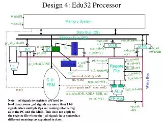
predQ Fetch I - Cache Decode Rename Active List Issue Queue Commit Functional Register Units File RVQ LdQ / StB LVQ To D - Cache Shadow Active List Commit Vector SRTR – Some issues • SRTR uses many additional data structures like the • Register Value Queue) (RVQ) • LVQ (Load Value Queue) • Store Buffer (StB) • Commit Vector (CV) • Prediction Queue (predQ) • Active List (AL) • Shadow Active List (SAL) • Hardware overhead is not addressed. • Relies on ECC for protection of critical data elements like CV entries and RVQ full/empty bits.
SRTR – Sphere of Replication • Protects the CPU registers • Sphere of replication does not extend to processor caches. • Register Value written by committed instruction can only be detected, cannot be recovered. • Issues in handling mispredictions have been addressed • Hardware overhead not addressed • Design of experiments and analysis is well done. • Fault injection results not presented
DIVA Approach: Basics • Core processor executes the program and creates the prediction instruction stream which is delivered (in program order) to the checker processor before retirement stage. • The prediction stream eliminates processing hazards, e.g., branch mispredictions, cache misses and data dependencies • Checker processor re-executes all the program computations • A simple in order processor pipeline which executes all pipeline stages for a given instruction at the same cycle. • Supports: (i) a register file, (ii) a small dedicated L0 cache, which is loaded with data the core pipeline touches. The L0 cache gets the output of the L1 cache (accessed by the core) and (iii) store queue.
DIVA Approach: Core Processor Prediction Stream To checker Processor
PC 0.5K I-Cache RF 4K D-Cache L0 Cache Checker Store Queue Checker Register File INST DIVA Approach: Checker Processor On-line checking mechanism inserted into the retirement stage of the microprocessor pipeline. L0 Cache Checker Store Queue Checker Register File INST
DIVA Approach: Error Handling • Error-free scenario – the checker processor does not detect an error in any of the pipeline stages • the instruction is retired and the state is copied to architectural state. • Error scenario – the checker processor detects an error in one of the pipeline stages • Re-execute on error to check the checker • Checker enters the execute state by reconfiguring itself to single serial instruction processing • the checker fixes the errant value in the prediction stream and commits the values (if there are no errors) • flushes the entire core pipeline • restarts itself and the core pipeline at the instruction following the errant instruction.
DIVA Approach: Some Issues • Pros and cons of a separate checker program counter (PC) • Checker does not maintain its own PC – following errors cannot be detected • An error in the program counter of the core pipeline • The core fetches an instruction from an erroneous location and forwards the PC and the instruction to the checker. The checker uses the same PC and fetches from the same location and hence the error is not detected. • An error causing an entry in the prediction stream to be overwritten by an entry of another instruction • an error can cause corruption of the index variable used to access the prediction stream buffer • the index points to an invalid entry or an entry corresponding to another valid (but random) instruction in the prediction stream • the checker uses the PC provided in the prediction stream and, hence, cannot detect this omission error. • Checker maintains its own PC • Relatively easy for a single-wide checker pipeline • Non-trivial for a wider checker pipeline (requires determining which checker pipeline should check which instruction)
Reliability and Security Engine (RSE): Basics • Hardware framework to support checking modules • Can be integrated with the processor or implemented as an FPGA-based engine • Hardware execution blocks • homogenous • contain embedded hardware modules for • error detection and recovery • Interface with the application through CHECK instructions • Interface with the external system through generic I/O interface • Modules are dynamically loadable and run-time re-configurable
Reliability and Security Engine: Internal Organization • Key components – manager module, checker modules, instruction queue, interconnects • Manager and checker modules are re-programmable • Instruction queue maintains currently executing instructions in pipeline
Inputs • Fetch_Out delivers the currently fetched instructions. • · Regfile_Data delivers the operands of an instruction. • · Execute_Out delivers results of ALU operations or address generation. • · Memory_Out provides data values loaded by the pipeline from memory during the current cycle. • · Commit_Out indicates the instructions that are committed or squashed by the pipeline; used to remove the data • corresponding to these instructions from the input queues. • Two additional inputs, Mem and Mem_Rdy, are used by the MAU (Memory Access Unit in the RSE) to access memory in response to requests from the hardware modules.
The Reliability and Security Engine (RSE) is implemented as an integral part of the processor, residing on the same die. • Le applicazioni sono consapevoli della presenza di tale sistema • Devono essere instrumentate opportunamente • As instructions are fetched from the pipeline, the CHECK instructions are forwarded to the RSE to invoke the security and reliability hardware checker modules. • Due modalità di funzionamento • In synchronous mode, the pipeline can commit only when the check executed by the module completes; this mode is used when errordetection is performed concurrent with instruction execution. • In asynchronous mode, the pipeline commits an instruction and sends a signal to the RSE. On receiving this signal, the RSE module collects permanent state used for checking and recovery; this mode is used when the module performs operations such as dependency tracking
Esempio • Instruction Checker Module (ICM) checks for errors in the binary of an instruction that enters the pipeline and operates in synchronous mode, i.e., the instruction should not be committed until checking in the module is complete. • Data Dependency Tracker (DDT) module, which logs dependency between the threads, operates in asynchronous mode. The dependency produced by an instruction is logged only when the instruction is committed in the pipeline so as not to keep speculative information in the module.
Manager • First Module to be instantiated • Configured at instantiation time • Main control of the RSE • Functions • Load modules • Provide input connections to execution modules • Service memory access requests to modules • Check progress of modules through heartbeat check
Hardware I/O Interface • Provides inputs from external system and communicate results back • Mapping input type to pins is done by manager module at instantiation of the RSE • Fetches inputs from the pipeline stages using • extra ports or additional fan-out for the pipeline outputs • Input queues updated every cycle with inputs from external system • Handles speculative execution by pipeline • Flushes input queues on flush of pipeline • Result of module execution checked by commit stage to commit or stall the instructions • On fault necessary action can be taken by pipeline • Flush instructions in pipeline • Invoke a recovery routine in RSE (e.g., going back to a checkpoint)
Instruction Checker Module • Checks binary of instruction being executed in pipeline • Module looks for instruction in input queue • Makes request for redundant copy of instruction from L2 Cache or memory • On receipt of redundant copy does comparison • Writes output of comparison to Instruction Queue • Instruction Queue results are checked by commit stage before committing the instruction
Data Range Checker Module • Checks bounds of memory accesses and instruction operands • Gets inputs from Memory Stage and Decode/Register Read Stage • Two ways of loading bounds • loaded by the programmer • extracted by variable analysis (e.g., statistical clustering) • CHECK instruction contains index of the variable to be checked. • Data loaded from memory, or register file sent to input queue on module from memory stage input • Checks bounds and writes result to Instruction queue
Sequence Checker Module • Compiler maintains information of the dependencies between instructions • need to check if the sequence of dependent instructions are executed (issued) in order • Approach • Compiler stores addresses of the sequences to be checked at runtime. • At load time address sequence is loaded into RSE module cache. • At execution time address of currently issued instruction is passed as a signal to RSE • RSE module goes to check the execution of the sequence.
Secure Return Address Module • Provides protection against buffer overflow attacks • Malicious user overwrites return address on stack to jump to malicious code • CHECK instructions are placed before CALL and RET instructions • For CALL instruction: • decodes CHECK instruction and pushes return address of following CALL instruction on local hardware stack called Secure Return Address Stack • For RETURN instruction • decodes CHECK instruction and waits for return address generated by instruction from execute stage • compares return address with address on top of SRAS • Mismatch indicates possible tampering with the return address • Handling speculative execution • Maintains a shadow return address stack • When there is a misspeculation shadow return address stack is flushed • When CALL instruction commits (got from commit stage input) return address is pushed to real stack.