Download
1 / 35
2.54k likes | 6.29k Views
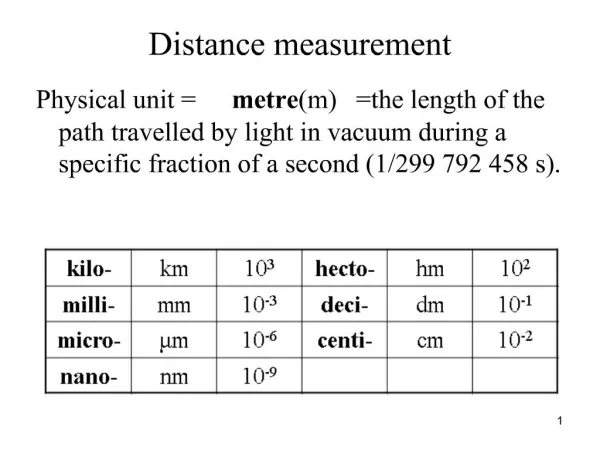
Electronic Distance Measurement (EDM). Ms Siti Kamariah Md Sa’at PPK Bioprocess Universiti Malaysia Perlis. Principle of operation: Velocity = distance / time. History. Theodolite & Tape Stadia EDM & Theodolite EDM, Theodolite & Data Collector.

E N D
Electronic Distance Measurement (EDM) Ms Siti Kamariah Md Sa’at PPK Bioprocess Universiti Malaysia Perlis
Principle of operation: Velocity = distance / time ERT 247-GEOMATICS ENGINEERING
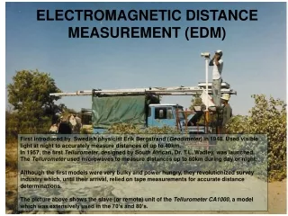
History Theodolite & Tape Stadia EDM & Theodolite EDM, Theodolite& Data Collector Prior to the total station, Theodolite with EDMs and data collectors were used to record large numbers of points, and for measuring long distances. The systems were heavy, prone to failure, and many times the parts incompatible. Prior to these systems, optical (stadia) and manual (tape) systems were used to measure distances. ERT 247-GEOMATICS ENGINEERING
History • First introduced in the late 1950’s • At first they were complicated, large, heavy, and suited primarily for long distances • Current EDM’s use either infrared (light waves) or microwaves (radio waves) • Microwaves require transmitters/receivers at both ends • Infrared use a transmitter at one end and a reflecting prism at the other and are generally used more frequently. ERT 247-GEOMATICS ENGINEERING
EDM Properties • They come in long (10-20 km), medium (3-10 km), and short range (.5-3 km). Range limits up to 50 km • They are typically mounted on top of a theodolite, but can be mounted directly to a tribrach. Total station = Theodolite with built in EDM + Microprocessor ERT 247-GEOMATICS ENGINEERING
EDM Classifications • Described by form of electromagnetic energy. • First instruments were primarily microwave (1947) • Present instruments are some form of light, i.e. laser or near-infrared lights. • Described by range of operation. • Generally microwave are 30 - 50 km range. (med) • Developed in the early 70’s, and were used for control surveys. • Light EDM’s generally 3 - 5 km range. (short) • Used in engineering and construction ERT 247-GEOMATICS ENGINEERING
EDM is very useful in measuring distances that are difficult to access or long distances. • It measures the time required for a wave to sent to a target and reflect back. ERT 247-GEOMATICS ENGINEERING
Principles of EDM Operation: A wave is transmitted and the returning wave is measured to find the distance traveled. ERT 247-GEOMATICS ENGINEERING
Principles of EDM Transmitted Energy Returned Energy ERT 247-GEOMATICS ENGINEERING
General Principle of EDM • Electromagnetic energy • Travels based on following relation: • Intensity modulate EM energy to specific frequency ERT 247-GEOMATICS ENGINEERING
Principles of EDM • Distances determined by calculating the number of wavelengths traveled. • Errors are generally small and insignificant for short distances. • For longer distances they can be more important. • Errors can be accounted for manually, or by the EDM if it has the capability. Velocity of light can be affected by: Temperature Atmospheric pressure Water vapor content ERT 247-GEOMATICS ENGINEERING
The Total Station Measures and Records: Horizontal Angles Vertical Angles and Slope Distances Calculates: Horizontal Distance Vertical Distance Azimuths of Lines X,Y,Z Coordinates Layout Etc.
EDM Characteristics • 750-1000 meters range • Accurate to ±5mm + 5 ppm • Operating temperature between -20 to +50 degrees centigrade • 1.5 seconds typical for computing a distanc, 1 second when tracking. • Slope reduction either manual or automatic. • Some average repeated measurements. • Signal attenuation. • battery operated and can perform between 350 and 1400 measurements. ERT 247-GEOMATICS ENGINEERING
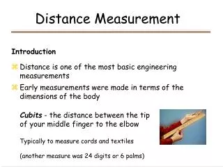
Prisms • Made from cube corners • Have the property of reflecting rays back precisely in the same direction. • They can be tribrach-mounted and centered with an optical plummet, or they can be attached • to a range pole and held vertical on a point with the aid of a bulls-eye level. ERT 247-GEOMATICS ENGINEERING
Prisms • Prisms are used with electro-optical EDM instruments to reflect the transmitted signal • A single reflector is a cube corner prism that has the characteristic to reflecting light rays precisely back to the emitting EDM instrument • The quality of the prism is determined by the flatness of the surface and the perpendicularity of the 90˚ surface ERT 247-GEOMATICS ENGINEERING
Accuracy • Distance is computed by (no. of wavelengths generated + partial wavelength)/2. • Standard or Random errors are described in the form of +(Constant + parts per million). • Constant is the accuracy of converting partial wavelength to a distance. • ppm is a function of the accuracy of the length of each wavelength, and the number of wavelengths. ERT 247-GEOMATICS ENGINEERING
EDM Accuracy ERT 247-GEOMATICS ENGINEERING
Blunders: • Incorrect ‘met’ settings • Incorrect scale settings • Prism constants ignored • Incorrect recording settings • (e.g. horizontal vs. slope) Error & Accuracy o-------------------------------o-------------o A B C Typical accuracy ± 5 mm + 5 ppm Both the prism and EDM should be corrected for off-center characteristics. The prism/instrument constant (about 30 to 40 mm) can be measured by measure AC, AB, and BC and then constant = AC-AB-BC ERT 247-GEOMATICS ENGINEERING
Sources of Error in EDM: • Personal: • Careless centering of instrument and/or reflector • Faulty temperature and pressure measurements • Incorrect input of T and p • Instrumental • Instrument not calibrated • Electrical center • Prism Constant (see next • slide) • Natural • Varying ‘met’ along line • Turbulence in air ERT 247-GEOMATICS ENGINEERING
Determination of System Measuring Constant C A B • Measure AB, BC and AC • AC + K = (AB + K) + (BC + K) • K = AC- (AB + BC) • If electrical center is calibrated, K rep- • resents the prism constant. Good Practice: Never mix prism types and brands on same project!!! Calibrate regularly !!! ERT 247-GEOMATICS ENGINEERING
Systematic Errors/Instrumentation Error • Microwave • Atmospheric conditions • Temperature • Pressure • Humidity - must have wet bulb and dry bulb temperature. • Multi-path • Reflected signals can give longer distances • Light • Atmospheric conditions • Temperature • Pressure • Prism offset • Point of measurement is generally behind the plumb line. • Today usually standardized as 30mm. ERT 247-GEOMATICS ENGINEERING
EDM instrument operation 1.Set up • EDM instruments are inserted in to the tribrach • Set over the point by means of the optical plummet • Prisms are set over the remote station point • The EDM turned on • The height of the prism and the EDM should me measured ERT 247-GEOMATICS ENGINEERING
EDM instrument operation 2.Aim • The EDM is aimed at the prism by using either the built-in sighting devices on the EDM • Telescope (yoke-mount EDMs) will have the optical line of sight a bit lower than the electronic signal • When the cross hair is sight on target the electronic signal will be maximized at the center of the prism • Set the electronic signal precisely on the prism center ERT 247-GEOMATICS ENGINEERING
EDM instrument operation 3. Measure • The slope measurement is accomplished by simply pressing the measure button • The displays are either liquid crystal (LCD) or light emitting diode (LED) • The measurements is shown in two decimals of a foot or three decimals of a meter • EDM with built in calculators can now be used to compute horizontal and vertical distances, coordinate, atmosphiric,curveture and prism constant corrections ERT 247-GEOMATICS ENGINEERING
EDM instrument operation 4. Record • The measured data can be recorded in the field note format • Can be entered manually into electronic data collector • The distance data must be accompanied by all relevant atmospheric and instrumental correction factors ERT 247-GEOMATICS ENGINEERING
Uses Topographic & As Builts Monitoring & Control Construction Layout ERT 247-GEOMATICS ENGINEERING
Uses • Total stations are ideal for collecting large numbers of points. • They are commonly used for all aspects of modern surveying. Only when harsh conditions, exist or distances are short will a transit and tape be used. ERT 247-GEOMATICS ENGINEERING
Problems • Total stations are dependant on batteries and electronics. The LCD screen does not work well when it is cold . • Battery life is also short, batteries and electronics both do not work well when wet. • Total stations are typically heavier that a transit and tape • Loss of data is an important consideration ERT 247-GEOMATICS ENGINEERING
Plane Geometry “The Flat Earth Society” Plane geometry vs. Spherical geometry Angles error ≈1” within 200 km2 area Distances Error ≈0.009mm per km ERT 247-GEOMATICS ENGINEERING
H O β A β A C α γ B Plane Geometry ERT 247-GEOMATICS ENGINEERING
Geometry of EDM Measurement • Relatively simple if hi = HR • More complicated when the EDM is on top of the theodolite and the prism is higher than the target (delta HR not equal to delta hi). ERT 247-GEOMATICS ENGINEERING
BS BS N Pt. A Pt. A R R α α Pt. 1 Pt. 1 Plane Coordinates Y X ERT 247-GEOMATICS ENGINEERING
N Horizontal Coordinates BS Pt. A β α+β ΔY HD α ΔX Pt. 1 β = BS Bearing α = HA α+β = Bearing of 1toA ERT 247-GEOMATICS ENGINEERING
Zenith Pt. A VA SD VD HD Pt. 1 Vertical Coordinates Zenith = Up Nadir = Down Horizon = 90° ERT 247-GEOMATICS ENGINEERING
Trigonometry Levelling Zenith HT SD Pt. A VD VA ΔZ HI HI HD Pt. 1 ERT 247-GEOMATICS ENGINEERING