Download
1 / 11
130 likes | 222 Views
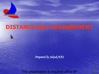
ELECTROMAGNETIC DISTANCE MEASUREMENT (EDM). First introduced by Swedish physicist Erik Bergstrand ( Geodimeter ) in 1948. Used visible light at night to accurately measure distances of up to 40km.

E N D
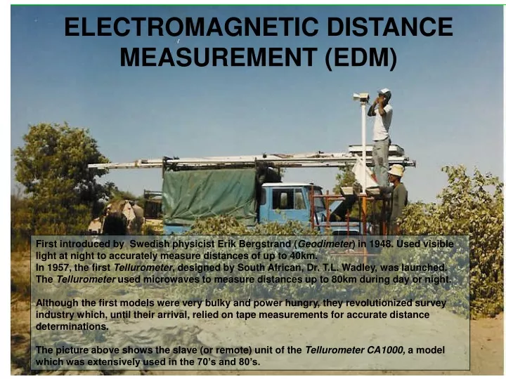
ELECTROMAGNETIC DISTANCE MEASUREMENT (EDM) First introduced by Swedish physicist Erik Bergstrand (Geodimeter) in 1948. Used visible light at night to accurately measure distances of up to 40km. In 1957, the first Tellurometer, designed by South African, Dr. T.L. Wadley, was launched. The Tellurometer used microwaves to measure distances up to 80km during day or night. Although the first models were very bulky and power hungry, they revolutionized survey industry which, until their arrival, relied on tape measurements for accurate distance determinations. The picture above shows the slave (or remote) unit of the Tellurometer CA1000, a model which was extensively used in the 70’s and 80’s.
SCALE DETERMINATION IN TRIGONOMETRICAL CONTROL NETWORKS Trigonometric Base Line Extension TRAVERSES TO EXPAND AND DENSIFY NATIONAL CONTROL NETWORKS INITIAL IMPACTS OF EDM EDM Traverses (and Trilateration)
Propagation of Electromagnetic Energy Velocity of EM energy, V = ƒ λƒ is the frequency in hertz (cycles/second) λis the wavelength In vacuum the velocity of electromagnetic waves equals the speed of light. V = c/n n >1, n is the refractive index of the medium through which the wave propagates c is the speed of light = 299 792 458 m/sec f λ = c/n or λ = cf/n (i.e. λvaries with n !) Note that n in any homogeneous medium varies with the wavelength λ. White light consists of a combination of wavelengths and hence n for visible light is referred to as a group index of refraction. For EDM purposes the medium through which electromagnetic energy is propagated is the earths atmosphere along the line being measured. It is therefore necessary to determine n of the atmosphere at the time and location at which the measurement is conducted.
Propagation of Electromagnetic Energy The refractive index of air varies with air density and is derived from measurements of air temperature and atmospheric pressure at the time and site of a distance measurement. For an average wavelength λ: na= 1 + ( ng-1 ) x p - 5.5e x 10-8 1 + 0.003661T 760 1 + 0.003661T Where ng is the group index of refraction in a standard atmosphere (T=0°C, p=760mm of mercury, 0.03% carbon dioxide) ng = 1+ ( 2876.04 + 48.864/λ2 +0.680/ λ4 ) x 10-7 p is the atmospheric pressure in mm of mercury (torr) T is the dry bulb temperature in °C and e is the vapor pressure Where e= e’+de and e’=4.58 x 10a, a=(7.5T’)/(237.3+T’), de=-(0.000660p (1+0.000115T’) (T-T’) and T’ is the wet-bulb temperature Hence measuring p, T and T’ will allow for the computation of n for a specific λ
THE FRACTION OF A WAVELENGTH AND THE PHASE ANGLE λ 90° + r θ ½λ ½λ 0° Amplitude 180° - r ¼λ ¼λ ¼λ ¼λ 270° θλ 360 A fraction of a wavelength can be determined from a corresponding phase angleθ Note: Forθ = 0° the fraction is 0 Forθ = 90° the fraction is ¼ Forθ = 180° the fraction is ½ Forθ = 270° the fraction is ¾ Forθ = 360° the fraction is 1 EDM INSTRUMENTS CAN MEASURE PHASE ANGLES
Principles of Electronic Distance Measurement 10 11 12 9 8 1 4 7 2 3 5 6 B A p λ λ λ λ λ λ λ λ λ λ λ λ L If an object moves at a constant speed of V over a straight distance L in a time interval ∆t, then L= V∆t = (c/n)∆t Knowing the speed of light c and being able to determine the refractive index, we could measure the time interval it takes for an electromagnetic wave to move from A to B to determine the distance L between A and B. But since c, the speed of light, is very high, the time interval ∆t would need to be measured extremely accurately. Instead, the principle of EDM is based on the following relationship: L = (m + p) λ m is an integer number of whole wavelengths, p is a fraction of a wavelength Thus L can be determined from λ, m and p
Solving for the integer number (m) of whole wavelengths(Resolving the ambiguity in the number of whole wave lengths) p3 λ2 p2 10 11 12 9 8 1 4 7 2 3 5 6 B A p1 λ λ λ λ λ λ λ λ λ λ λ λ L Additional waves of known lengths λ3= kλ2 and λ2= k λ1(k is a constant), are introduced to measure the same distance L: L = (m3 + p3) λ3 L =(m2 + p2) λ2 L =(m1 + p1) λ1 Determiningp1 p2andp3by measuring phase anglesθ1θ2andθ3and solving the above equations simultaneously yields L ( Note: For L < λ3 , m3 = 0). For example, if λ1= 10.000m, k= 10.000 and p1 = 0.2562, p2 = 0.2620 and p3 = 0.0125 Then λ2= 10.000m x 10.000 = 100.000m and λ3= 100.000 x 10.000 = 1000.000 L= (m3 + p3) λ3= (0+0.1250)x 1000.000 = 125.000m approximately m2= 125/ λ2=125/100=1 and hence L = (1+0.2620)x100.000 = 126.200m approximately m1= 126.2/ λ1=126.2/10=12 and hence L = (12+ 0.2562)x10 = 122.562m
Basic Components of an EDM Instrument Reflector Reflector L Beam Splitter Length of measured path is 2xL Variable Filter Interference Filter Transmitter L F4 F1 Receiver Optics and phase-difference circuits F2 F3 Measurement signal Reference signal Frequency Generator Phase Meter Display To obtain the phase angle the reflected signal phase is compared to the reference signal phase. Note also that the measured distance equals 2 x L.
General Remarks on EDM • The original Tellurometer models, using microwaves, consisted of two units, the master and the remote, both of which had to be manned. The carrier wave was used to establish a voice channel between the operators who had to coordinate the manual switching of the frequencies. The measuring signals were directed (bundled) by means of metal cones. For long lines careful measurements of pressure and the wet- and dry-bulb temperatures were made at each end of the line. Measurements were very susceptible to multipath reflections (ground swing). • Developments in electronics reduced the size of the components drastically so that EDM instruments could be mounted on top of theodolites for convenient simultaneous measurements of distances as well as directions. Nowadays EDM components are completely integrated into total stations. • Total stations allow for the direct input of temperature and pressure and automatic application of meteorological corrections. • Most of the current EDM instruments use LASER beams and passive optical reflectors, thus reducing the possibility of multipathing considerably. • The latest models provide for reflector-less measurements, thus improving efficiency for certain applications drastically.
Sources of Error in EDM: Instrumental • Instrument not calibrated • Electrical center • Prism Constant (see next slide) Personal: • Careless centering of instr. and/or reflector • Faulty temperature and pressure measurements • Incorrect input of T and p Natural • Varying ‘met’ along line • Turbulence in air Remember: L = (m + p) λ
Sources of Error in EDM: Determination of System Measuring Constant C A B Mistakes: • Incorrect ‘met’ settings • Incorrect scale settings • Prism constants ignored • Incorrect recording settings (e.g. horizontal vs. slope) • Measure AB, BC and AC • AC + K = (AB + K) + (BC + K) • K = AC- (AB + BC) • If electrical center is calibrated, K rep- • resents the prism constant. Good Practice: Never mix prism types and makes on same project!!! Calibrate regularly !!!