Download
1 / 13
140 likes | 281 Views
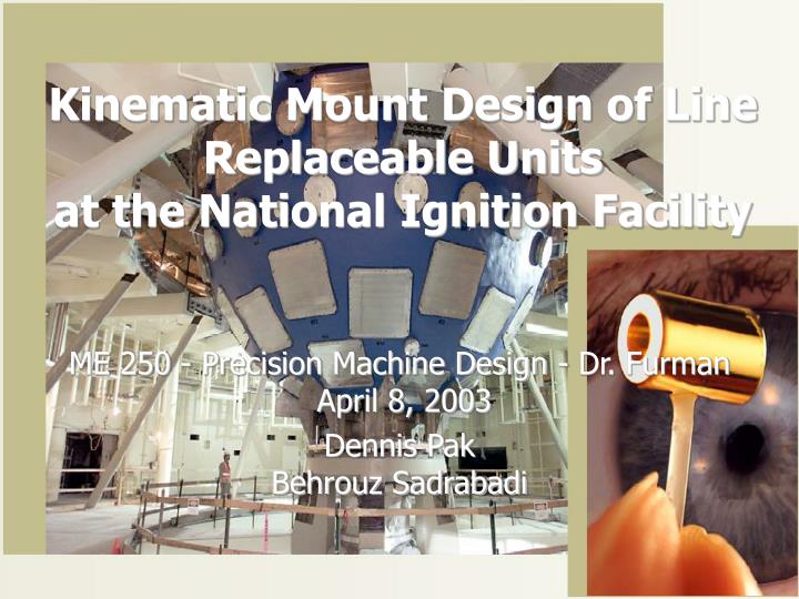
Kinematic Mount Design of Line Replaceable Units at the National Ignition Facility. ME 250 - Precision Machine Design - Dr. Furman April 8, 2003 Dennis Pak Behrouz Sadrabadi. National Ignition Facility. Located at Lawrence Livermore National Lab $3.9 Billion DOE Defense Programs project

E N D
Kinematic Mount Design of Line Replaceable Unitsat the National Ignition Facility ME 250 - Precision Machine Design - Dr. Furman April 8, 2003 Dennis PakBehrouz Sadrabadi
National Ignition Facility • Located at Lawrence Livermore National Lab • $3.9 Billion DOE Defense Programs project • 192 laser beams will all converge onto a BB-sized capsule • Power output 1000 times the electric generating power of the U.S.
NIF Missions • Primary mission: support the Stockpile Stewardship Program • Maintain safety and reliability of U.S.’s nuclear arsenal • 85% of experiments: nuclear weapons physics • Will provide experimental data necessary to complete computer simulations • Inertial fusion energy (IFE) • Determine feasibility of IFE as an energy source • Basic scientific research • Experiments in high-energy-density physics for astrophysics, hydrodynamics, plasma physics, material properties, radiation physics
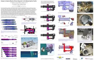
NIF Laser System - LRUs • Each beamline contains 40 large optical elements • Light path must have clean room atmosphere - beamlines are sealed Optics needed to be removable for repair and cleaning Line Replaceable Unit (LRU) concept was thus adopted - can be installed and removed with a semi-automated robotic unit
Line Replaceable Units (LRUs) • Kinematic mount is essentially a three-vee coupling • Two vee grooves at bottom of LRU resting on retractable pins on laser structure • Upper mount consists of two pin-slot constraints, effectively creating a wide vee
Kinematic Coupling Evolution • The LRU kinematic coupling evolved from the basic three-vee coupling • Coupling was rotated to better accommodate tall LRU geometry • Lower vees were rotated to carry gravity load • Upper vee was spread wide to decrease rotational inertia and increase torsional stiffness
Mount Points in Vertical Plane • Placing mount points into vertical plane provides a more favorable aspect ratio. • Provides for smallest footprint - dense packing of LRUs in beamline
Wide Upper Vee - Inertia • Upper vee spread with pin-slot constraints • Instant center of rotation is thus brought closer to the principal axis of LRU • Rotational inertia reduced, vibrational frequency increased
Wide Upper Vee - Stiffness • Primary motivation for wide vee is to maximize torsional stiffness. • Torsional stiffness of pin-slot constraint is an order of magnitude greater than LRU structure • Maximum potential static twist due to friction remains well below the maximum allowable
Modeling of Coupling • Kinematic mount modeled as parallel combination of 6 springs • Load vector: 3 forces, 3 moments • Deflection vector: 3 displacements, 3 rotations • 6 X 6 stiffness matrix for a mount point determined in local coordinate system • Stiffness matrices transformed into global coordinates, combined by addition
Optimization:Variable Parameters • Locations of mounts already established by overall geometry of LRU • The remaining geometric attributes were set as variable parameters subject to optimization • Lower mount pin angle • Lower mount outside vee angle • Lower mount inside vee angle • Upper mount slot angle
Optimization: Centering Ability • LRUs optimized for maximum limiting coefficient of friction -> maximum centering ability • As LRU contacts engage, minimum limiting C.O.F. occurs when 5 contacts are engaged • Limiting C.O.F. for a given set of variable parameters taken to be minimum of six values • Although optimization algorithm could have been used, graphical approach was taken instead
Summary • LRUs needed to be easily installed and removed with a high degree of repeatability by a robotic system • Basic configuration of three-vee coupling was determined by overall geometry of LRU • The remaining, unspecified parameters were determined by optimizing for maximum centering ability • In general, the performance of a kinematic mount can be maximized through analysis and optimization