Download
1 / 1
10 likes | 78 Views

E N D
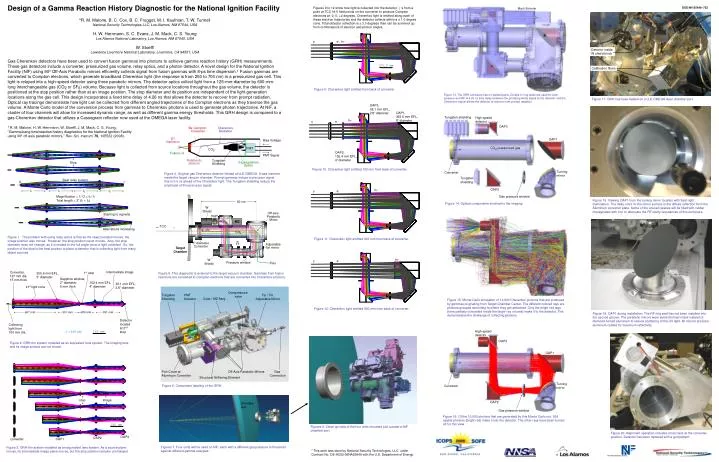
Figures 9 to 12 show how light is collected into the detector. ’s from a point at TCC hit 5 field points on the converter to produce Compton electrons at -2, 0, +2 degrees. Cherenkov light is emitted along each of these electron trajectories and the detector collects within a ± 1.0 degree cone. Total detector collection is ± 3.0 degrees than can be summed up from combinations of electron and photon angles. Tungsten shielding High-speed detector Overpressure valve Tungsten Shielding PMT Detector Tip / Tilt Adjustable Mirror Mach-Zehnder Stop Intermediate image Converter, 127 mm dia. 15 mm thick Coax / MZ Assy 1st stop 355.6 mm EFL, 5” diameter OAP3, 38.1 mm EFL, 2.6” diameter OAP3 60 cm Sapphire window, 2” diameter, 5 mm thick 152.4 mm EFL, 4” diameter W Shield OAP1, 355.6 mm EFL, 5” diameter 38.1 mm EFL, 2.6” diameter Be Compton Converter Cherenkov Radiation ±1º light cone OAP1 Off-axis Parabolic Mirror Best relay system h h h O I e- e- e- PMT DT Implosion Bias Voltage e-, h MZ Detector inside W shield block CO2 pressurized gas f1 f1 f2 f2 stop image TCC PMT CO2 e→h Magnification = I / O = f2 / f1 CO2 Fusion g’s Total length = 2* (f1 + f2) PMT Signal 607 mm 301 mm 206 mm 351 mm Calibration fibers Relativistic electron Tungsten Shielding Cassegrainian Optics 5” diameter Converter Detector located at 2nd stop Adjustable flat mirror 100.0 mm Turning mirror Converter OAP2, 152.4 mm EFL, 4” diameter Starting to vignette Target Chamber Collecting light from 100 mm dia. 180 mm Tungsten shielding Figure 4. Original gas Cherenkov detector fielded at LLE OMEGA. It was inserted inside the target vacuum chamber. Prompt gammas induce a precursor signal that is 0.5 ns ahead of the Cherenkov light. The Tungsten shielding reduce the amplitude of this precursor signal. The National Ignition Facility l = 410 nm 180 mm W Shield OAP3 OAP2 Aberrations increasing Port Cover w/ Aluminum Converter Off-Axis Parabolic Mirrors Gas Connection Pressure window Fidu converter OAP2 OAP1 Figure 12. Cherenkov light emitted 500 mm from back of converter. Figure 11. Cherenkov light emitted 300 mm from back of converter. Figure 10. Cherenkov light emitted 100 mm from back of converter. Figure 2. GRH-6m system modeled as an equivalent lens system. The imaging lens and its image surface are not shown. Structural Stiffening Element Figure 9. Cherenkov light emitted from back of converter. Figure 1. The problem with using relay optics is that as the object position moves, the image position also moves. However, the stop position never moves. Also, the stop diameter does not change, as it is related to the full angle cone of light collected. So, the position of the stop is the best position to place a detector that is collecting light from many object sources. Figure 17. GRH has been fielded on a LLE OMEGA laser chamber port. Gas pressure window Figure 3. GRH-6m system modeled as an equivalent lens system.As a source plane moves, its intermediate image plane moves, but the stop position remains unchanged. Figure 13. The GRH enclosure has no welded parts. Double O-ring seals are used for both pressure and RF. A 4.26 ns time delay between the prompt gamma signal at the detector and the Cherenkov signal allows the detector to recover from prompt radiation. Figure 5. This diagnostic is external to the target vacuum chamber. Gammas from fusion reactions are converted to Compton electrons that are converted into Cherenkov photons. Figures 8. Close up view of the four units mounted just outside a NIF chamber port. Figure 6. Component labeling of the GRH. Figure 14. Optical components involved in the imaging. Figure 18. Viewing OAP1 from the turning mirror location with flash light illumination. The milky color on the mirror surface is the diffuse reflection from the Aluminum converter plate. Some of the unused spaces will be filled with rubber impregnated with iron to attenuate the RF cavity resonances of this enclosure. Figure 15. Monte Carlo simulation of 10,000 Cherenkov photons that are produced by gammas originating from Target Chamber Center. The different colored rays are photons grouped according to where they get absorbed. Only the bright red rays (here partially concealed inside the larger ray volume) make it to the detector. This demonstrates the challenge of collecting photons. Figure 19. OAP1 during installation. The RF ring seal has not been installed into the second groove. The parabolic mirrors were electroformed nickel instead of diamond-turned aluminum to reduce scattering of the UV light. All mirrors are bare aluminum coated for maximum reflectivity. High-speed detector OAP3 OAP1 Turning mirror Converter OAP2 Gas pressure window Figure 16. Of the 10,000 photons that are generated by this Monte Carlo run, 524 usable photons (bright red) make it into the detector. The other rays have been turned off for this view. Figure 20. Alignment operation includes cross hairs at the converter position. Detector has been replaced with a grid pattern. Figures 7. Four units will be used on NIF, each with a different gas pressure to threshold against different gamma energies. Design of a Gamma Reaction History Diagnostic for the National Ignition Facility *R. M. Malone, B. C. Cox, B. C. Frogget, M. I. Kaufman, T. W. Tunnell National Security Technologies LLC, Los Alamos, NM 87544, USA H. W. Herrmann, S. C. Evans, J. M. Mack, C. S. Young Los Alamos National Laboratory, Los Alamos, NM 87545, USA W. Stoeffl Lawrence Livermore National Laboratory, Livermore, CA 94551, USA Gas Cherenkov detectors have been used to convert fusion gammas into photons to achieve gamma reaction history (GRH) measurements. These gas detectors include a converter, pressurized gas volume, relay optics, and a photon detector. A novel design for the National Ignition Facility (NIF) using 90º Off-Axis Parabolic mirrors efficiently collects signal from fusion gammas with 8-ps time dispersion.1 Fusion gammas are converted to Compton electrons, which generate broadband Cherenkov light (the response is from 250 to 700 nm) in a pressurized gas cell. This light is relayed into a high-speed detector using three parabolic mirrors. The detector optics collect light from a 125-mm-diameter by 600-mm-long interchangeable gas (CO2 or SF6) volume. Because light is collected from source locations throughout the gas volume, the detector is positioned at the stop position rather than at an image position. The stop diameter and its position are independent of the light-generation locations along the gas cell. This design incorporates a fixed time delay of 4.26 ns that allows the detector to recover from prompt radiation. Optical ray tracings demonstrate how light can be collected from different angled trajectories of the Compton electrons as they traverse the gas volume. A Monte Carlo model of the conversion process from gammas to Cherenkov photons is used to generate photon trajectories. At NIF, a cluster of four channels will allow for increased dynamic range, as well as different gamma energy thresholds. This GRH design is compared to a gas Cherenkov detector that utilizes a Cassegrain reflector now used at the OMEGA laser facility. 1R. M. Malone, H. W. Herrmann, W. Stoeffl, J. M. Mack, C. S. Young, “Gamma bang time/reaction history diagnostics for the National Ignition Facility using 90º off-axis parabolic mirrors,” Rev. Sci. Instrum.79, 10E532 (2008). DOE/NV/25946–732 Chamber wall * This work was done by National Security Technologies, LLC, under Contract No. DE-AC52-06NA25946 with the U.S. Department of Energy.