Download
1 / 21
220 likes | 401 Views
Cisco TCS Project – Semester 3. LAN Design of a Local High School. Martin Kucek Chris C. Yu Sandy Ramirez. © 2001 Martin Kucek / Chris C. Yu / Sandy Ramirez. All Rights Reserved. General Requirements.

E N D
Cisco TCS Project – Semester 3 LAN Design of a Local High School Martin Kucek Chris C. Yu Sandy Ramirez © 2001 Martin Kucek / Chris C. Yu / Sandy Ramirez. All Rights Reserved
General Requirements • Design the LAN at a minimum of cost to the school serving 306 nodes (288 workstations for students, 12 workstations for teachers, 3 servers, 3 printers) • A minimum of 1.0 Mbps to any host computer in the LAN and 100Mbps to any server host in the LAN • Access to the Internet from any host computer in the LAN • Implementing an enterprise server (DNS/E-mail) and workgroup servers (Staff, Students) • Implementing TCP/IP routed protocol • Functionality of the LAN for a minimum 7-10 years: • 100% growth in LAN throughput • 1000% growth in the Internet connection throughput © 2001 Martin Kucek / Chris C. Yu / Sandy Ramirez. All Rights Reserved
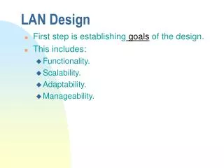
General LAN Design Goals • Functionality: The network must work. The network must provide user-to-user and user-to-application connectivity with reasonable speed and reliability. • Scalability: The network must be able to grow. The initial design should grow without any major changes to the overall design. • Adaptability: The network must be designed to accommodate future technologies, and it should include no element that would limit implementation of new technologies as they become available. • Manageability: The network must be monitored and managed to ensure ongoing stability of operation. © 2001 Martin Kucek / Chris C. Yu / Sandy Ramirez. All Rights Reserved
Security Requirements • 2 LAN segments in the school • 2 VLANs for secure separation between: • Student/curriculum VLAN#2 • Staff/administrative VLAN#3 • Access from the Internet to LAN not allowed • Administrative Server must be accessible only to staff • Student Server must be available to the entire school network © 2001 Martin Kucek / Chris C. Yu / Sandy Ramirez. All Rights Reserved
School Layout • One 3-floor building • Each floor has 4 identical classrooms • MDF – 2nd floor • IDF – 1st and 3rd floor Classrooms: • 24 workstations for students • 1 workstation for teacher (staff) • 24-port hub located in a lockable cabinet • 4 cable runs to each classroom (two cable runs reserved) • Printers location: 1st floor : classroom 108 2nd floor : classroom 208 3rd floor : classroom 308 © 2001 Martin Kucek / Chris C. Yu / Sandy Ramirez. All Rights Reserved
Main Distribution Facility (MDF) • Central Point of wires termination • Router Cisco 2621 (Dual 10/100 Fast Ethernet Ports, 2 Serial Ports) • Switch Catalyst 2912 (12 autosensing ports 10/100 Mbps) • Hub 3Com Dual Speed (8 autosensing ports 10/100 BASE-TX, RJ-45) • VCC (Vertical Cross Connect) • HCC (Horizontal Cross Connect) • POP (Point of Presence) • DNS Server/E-mail Server • Student Server - Curriculum • Staff Server – Administration • UPS • Backup Tapes © 2001 Martin Kucek / Chris C. Yu / Sandy Ramirez. All Rights Reserved
Intermediate Distribution Facility (IDF) • Switch Catalyst 2912 (12 autosensing ports 10/100 Mbps) • Hub 3Com Dual Speed (8 autosensing ports 10/100 BASE-TX, RJ-45) • VCC (Vertical Cross Connect) • HCC (Horizontal Cross Connect) • UPS © 2001 Martin Kucek / Chris C. Yu / Sandy Ramirez. All Rights Reserved
Cut Sheet of a floor © 2001 Martin Kucek / Chris C. Yu / Sandy Ramirez. All Rights Reserved
LAN Physical Topology © 2001 Martin Kucek / Chris C. Yu / Sandy Ramirez. All Rights Reserved © 2001 Martin Kucek / Chris C. Yu / Sandy Ramirez. All Rights Reserved
LAN Cabling • Vertical Cabling (Backbone): Cabling between MDF & IDFs • 100BASE-T ports: • RJ-45 connectors; two-pair Category 5 UTP cabling • Horizontal Cabling: Cabling between hosts and MDF (IDFs) • conducted in drop ceilings • 100BASE-T ports: • RJ-45 connectors; two-pair Category 5 UTP cabling © 2001 Martin Kucek / Chris C. Yu / Sandy Ramirez. All Rights Reserved
LAN Scheme © 2001 Martin Kucek / Chris C. Yu / Sandy Ramirez. All Rights Reserved
Cut Sheet for IDF 1(1st floor) © 2001 Martin Kucek / Chris C. Yu / Sandy Ramirez. All Rights Reserved
Cut Sheet for MDF(2nd floor) © 2001 Martin Kucek / Chris C. Yu / Sandy Ramirez. All Rights Reserved
Cut Sheet for IDF 2(3rd floor) © 2001 Martin Kucek / Chris C. Yu / Sandy Ramirez. All Rights Reserved
IP Addressing Scheme 2 class C addresses: Network 1: 192.168.100.0 Network 2: 192.168.110.0 Network 1 - (floor 1 & 2, router interface - E0): Host range of 192.168.100.1 – 192.168.100.254 (254 nodes) Network 2 - (floor 3, router interface - E1): Host range of 192.168.110.1 – 192.168.110.254 (254 nodes) © 2001 Martin Kucek / Chris C. Yu / Sandy Ramirez. All Rights Reserved
IP Addressing Scheme (cont.) Network 1 (floor 1 & 2): Router E0: 192.168.100.1 Router S0: 192.168.100.2 Router S1: not assigned Switch 1: 192.168.100.6 Switch 2: 192.168.100.7 DNS/E-mail Server: 192.168.100.3 (Shared) Students/Curriculum Server: 192.168.100.4 (Shared) Staff/Administrative Server: 192.168.100.5 (VLAN#2) Printer 1: 192.168.100.8 (Shared) Printer 2: 192.168.100.9 (Shared) (VLAN#2 Staff/Administrative) assigned IP in range of: 192.168.100.10 – 192.168.100.17 (8 nodes) (VLAN#3 Students/Curriculum) assigned IP in range of: 192.168.100.18 – 192.168.100.254 (236 nodes) © 2001 Martin Kucek / Chris C. Yu / Sandy Ramirez. All Rights Reserved
IP Addressing Scheme (cont.) Network 2 (floor 3): Router E1: 192.168.110.1 Switch 3: 192.168.110.2 Printer 3: 192.168.110.3 (Shared) (VLAN#2 Staff/Administrative) assigned IP in range of: 192.168.110.4 - 192.168.110.7 (4 nodes) (VLAN#3 Students/Curriculum) assigned IP in range of: 192.168.110.8 - 192.168.110.254 (246 nodes) © 2001 Martin Kucek / Chris C. Yu / Sandy Ramirez. All Rights Reserved
Security Solution Secure separation between students and staff/administrative: - done by VLANS Firewall: Create Access Control List to deny external access to local LAN: access-list 1 permit 192.168.100.0 0.0.0.255 access-list 1 permit 192.168.110.0 0.0.0.255 int E0 ip access-group 1 in int E1 ip access-group 1 in © 2001 Martin Kucek / Chris C. Yu / Sandy Ramirez. All Rights Reserved
LAN Equipment Costs © 2001 Martin Kucek / Chris C. Yu / Sandy Ramirez. All Rights Reserved
Network Analysis Advantages: • The bandwidth is well surpassing the requirement for each host from the outset. • Security and efficiency are enhanced through switching and VLANs. • Reserved cables are already in place for effortless expansion. • The entire design is highly economical and cost effective for any budget strapped school. • It is a simple, inexpensive and high performance small network. Disadvantages: • No redundancy to the Internet - if the WAN link fails, access to the resources outside the LAN is lost. • Student Workstations - Classroom Collision Domain © 2001 Martin Kucek / Chris C. Yu / Sandy Ramirez. All Rights Reserved
The EndQuestions??? Shoot!!! © 2001 Martin Kucek / Chris C. Yu / Sandy Ramirez. All Rights Reserved