Download
1 / 13
130 likes | 313 Views
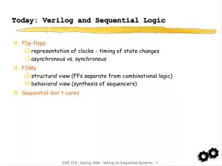
Today: Verilog and Sequential Logic. Flip-flops representation of clocks - timing of state changes asynchronous vs. synchronous FSMs structural view (FFs separate from combinational logic) behavioral view (synthesis of sequencers) Sequential don't cares. Incorrect Flip-flop in Verilog.

E N D
Today: Verilog and Sequential Logic • Flip-flops • representation of clocks - timing of state changes • asynchronous vs. synchronous • FSMs • structural view (FFs separate from combinational logic) • behavioral view (synthesis of sequencers) • Sequential don't cares CSE 370 - Spring 1998 - Verilog for Sequential Systems - 1
Incorrect Flip-flop in Verilog • Use always block's sensitivity list to wait for clock to change module dff (CLK, d, q); input CLK, d; output q; reg q; always @(CLK) q = d; endmodule Not correct! Q will change whenever the clock changes, not just on the edge. CSE 370 - Spring 1998 - Verilog for Sequential Systems - 2
Correct Flip-flop in Verilog • Use always block's sensitivity list to wait for clock edge module dff (CLK, d, q); input CLK, d; output q; reg q; always @(posedge CLK) q = d; endmodule CSE 370 - Spring 1998 - Verilog for Sequential Systems - 3
More Flip-flops • Synchronous/asynchronous reset/set • single thread that waits for the clock • three parallel threads – only one of which waits for the clock Synchronous Asynchronous module dff (CLK, s, r, d, q); input CLK, s, r, d; output q; reg q; always @(posedge CLK) if (r) q = 1'b0; else if (s) q = 1'b1; else q = d; endmodule module dff (CLK, s, r, d, q); input CLK, s, r, d; output q; reg q; always @(posedge r) q = 1'b0; always @(posedge s) q = 1'b1; always @(posedge CLK) q = d; endmodule CSE 370 - Spring 1998 - Verilog for Sequential Systems - 4
Example: A parity checker • Serial input string • OUT=1 if odd # of 1s in input • OUT=0 if even # of 1s in input 1. State diagram and state-transition table Present Input Next Present State State Output Even 0 Even 0 Even 1 Odd 0 Odd 0 Odd 1 Odd 1 Even 1 CSE 370 - Spring 1998 - Verilog for Sequential Systems - 5
Example: A parity checker (continued) 2. State minimization:Already minimized • Need both states (even and odd) • Use one flip-flop 3. State assignment (or state encoding) Present Input Next Present State State Output 0 0 0 0 0 1 1 0 1 0 1 1 1 1 0 1 CSE 370 - Spring 1998 - Verilog for Sequential Systems - 6
Example: A parity checker (continued) 4. Next-state logic minimization • Assume D flip-flops • Next state = (present state) XOR (present input) • Present output = present state 5. Implement the design CSE 370 - Spring 1998 - Verilog for Sequential Systems - 7
Verilog Structural View of a FSM • General view of a finite state machine in verilog module FSM (CLK, in, out); input CLK; input in; output out; reg out; // state variable reg [1:0] state; // local variable reg [1:0] next_state; always @(posedge CLK) // registers state = next_state; always @(state or in) // Compute next-state and output logic whenever state or inputs change. // (i.e. put equations here for next_state[1:0]) // Make sure every local variable has an assignment in this block!endmodule CSE 370 - Spring 1998 - Verilog for Sequential Systems - 8
zero[0] 0 1 0 one1[0] 0 1 1 two1s [1] Moore Verilog FSM • Reduce 1’s example `define zero 0`define one1 1`define two1s 2module reduce (CLK, reset, in, out); input CLK, reset, in; output out; reg out; reg [1:0] state; // state variables reg [1:0] next_state; always @(posedge CLK) if (reset) state = `zero; else state = next_state; state assignment CSE 370 - Spring 1998 - Verilog for Sequential Systems - 9
Moore Verilog FSM (continued) always @(in or state) case (state) `zero: // last input was a zero begin if (in) next_state = `one1; else next_state = `zero; end `one1: // we've seen one 1 begin if (in) next_state = `two1s; else next_state = `zero; end `two1s: // we've seen at least 2 ones begin if (in) next_state = `two1s; else next_state = `zero; end endcase crucial to include all signals that are input to state and output equations note that output onlydepends on state always @(state) case (state) `zero: out = 0; `one1: out = 0; `two1s: out = 1; endcase endmodule CSE 370 - Spring 1998 - Verilog for Sequential Systems - 10
0/0 zero 1/0 0/0 one1 1/1 Mealy Verilog FSM module reduce (CLK, reset, in, out); input CLK, reset, in; output out; reg out; reg state; // state variables reg next_state; always @(posedge CLK) if (reset) state = `zero; else state = next_state; always @(in or state) case (state) `zero: // last input was a zero begin out = 0; if (in) next_state = `one; else next_state = `zero; end `one: // we've seen one 1 if (in) begin next_state = `one; out = 1; end else begin next_state = `zero; out = 0; end endcaseendmodule Remember the Highlight- The-Arrows Method Input Output CSE 370 - Spring 1998 - Verilog for Sequential Systems - 11
Blocking and Non-Blocking Assignments • Blocking assignments (X=A) • completes the assignment before continuing on to next statement • Non-blocking assignments (X<=A) • completes in zero time and doesn’t change the value of the target until a blocking point (delay/wait) is encountered • Example: swap always @(posedge CLK) begin temp = B; B = A; A = temp; end always @(posedge CLK) begin A <= B; B <= A; end CSE 370 - Spring 1998 - Verilog for Sequential Systems - 12
RTL Assignment • Non-blocking assignment is also known as an RTL assignment • if used in an always block triggered by a clock edge • mimic register-transfer-level semantics – all flip-flops change together // B,C,D all get the value of Aalways @(posedge clk) begin B = A; C = B; D = C; end // this implements a shift registeralways @(posedge clk) begin {D, C, B} = {C, B, A}; end // implements a shift register tooalways @(posedge clk) begin B <= A; C <= B; D <= C; end CSE 370 - Spring 1998 - Verilog for Sequential Systems - 13