Download
1 / 23
300 likes | 908 Views
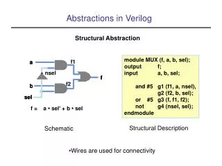
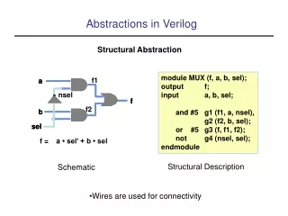
Timing control in verilog. Module 3.1 Delays in Verilog. Procedural blocks and timing controls. Delay controls. Edge-Sensitive Event controls. Level-Sensitive Event controls-Wait statements. Named Events. Timing Controls. Delay-Based –Regular delay control •AKA Inertial Delay

E N D
Timing control in verilog Module 3.1 Delays in Verilog
Procedural blocks and timing controls. • Delay controls. • Edge-Sensitive Event controls. • Level-Sensitive Event controls-Wait statements. • Named Events.
Timing Controls • Delay-Based –Regular delay control •AKA Inertial Delay –Intra-assignment delay control •AKA Transport delay –Zero delay control
Regular Delay Control parameter latency = 20; parameter delta = 2; regx,y,z,p,q; Initial Begin x=0; // no delay control #10 y = 1; //delay control with a constant #latency z = 0; //delay control with identifier #(latency + delta) p = 1; //delay control with expression #y x = x + 1; //delay control with identifier end
Intra-assignment delay control • Assigning delay to the right of the assignment operator • The intra-assignment delay computes the right-hand-side expression at the current time and defer the assignment of the computed value to the left-hand-side variable. • Equivalent to regular delays with a temporary variable to store the current value of a right-hand-side expression
Timing Control • Verilog is a discrete event time simulator. If there is no timing control, simulation time does not advance. • Simulated time can only progress by one of the following: • gate or wire delay, if specified • a delay control, introduced by the # symbol. • an event control, introduced by the @ symbol. • the wait statement. • The order of execution of events in the same clock time may not be predictable.
Delay based Timing Control • Delay Control (#) • Expression specifies the time duration between initially encountering the statement and when the statement actually executes. • Delay in Procedural Assignments • Inter-Statement Delay • Intra-Statement Delay • For example: • Inter-Statement Delay #10 A = A + 1; • Intra-Statement Delay A = #10 A + 1;
Event-Based Timing Control (cont.) • Events (@) • Change in the value of a register or net • Used to trigger execution of a statement or block (reactive behavior/reactivity) • Types of Event-based timing control • Regular event control • Named event control • Event OR control • Level-sensitive timing control (wait statement)
Event-Based Timing Control (cont.) • Regular event control • Symbol: @(<event>) • Events to specify: • posedge sig: • Change of sig from any value to 1or from 0 to any value • negedge sig: • Change of sig from any value to 0or from 1 to any value • sig: Any chage in sig value
Event-Based Timing Control (cont.) • Regular event control Examples: @reg_a begin A = B&C; end @(posedge clock1) A = B&C; @(negedge clock2) A = B&C; Forever @(negedge clock3) begin A = B&C; end
Event-Based Timing Control (cont.) • Named event control • You can declare (name) an event, and then trigger and recognize it. • Verilog keyword for declaration: event • event event1; • Verilog symbol for triggering: -> • ->event1 • Verilog symbol for recognizing: @() • @(event1) begin <some procedural statements> end
Event-Based Timing Control (cont.) • Event OR control • Used when need to trigger a block upon occurrence of any of a set of events. • The list of the events: sensitivity list • Verilog keyword: or • Look at the handout • Event OR control Example: always @ ( reset or clock ) begin if ( reset ) q= 1’b0; else q= d; end
Timing Control (cont.) • wait Statement • The wait statement allows a procedural statement or a block to be delayed until a condition becomes true. • The difference between the behavior of a wait statement and an event is that the wait statement is level sensitive whereas @(posedge clock); is triggered by a signal transition or is edge sensitive. • For Example: • wait (A == 3) begin A = B&C; End
Delay back- annotation is an important and vast topic in timing simulation. in this section, we introduce the designer to the concept of back-annotation of delays in a simulation. Delay Back-Annotation
The various steps in the flow that use delay back-annotation are as follows: 1. The designer writes the RTL description and then performs functional simulation. 2. The RTL description is converted to a gate level netlist by a logic synthesis tool. 3. The designer obtains prelayout estimates of delays in the chip by using a delay calculator and information about the IC fabrication process. Then, the designer does timing simulation or static timing verification of the gate-level netlist, using these preliminary values to check that the gate-level netlist meets timing constraints.
4. The gate-level netlist is then converted to layout by a place and route tool. The postlayout delay values are computed from the resistance (R) and capacitance (C) information in the layout. The R and C information is extracted from factors such as geometry and IC fabrication process. 5. The post-layout delay values are back-annotated to modify the delay estimates for the gate-level netlist. Timing simulation or static timing verification is run again on the gate-level netlist to check if timing constraints are still satisfied. 6. If design changes are required to meet the timing constraints, the designer has to go back to the RTL level, optimize the design for timing, and then repeat Step 2 through Step 5.