Download

1 / 17
210 likes | 456 Views
Delays in Verilog. Introduction. Delays are crucial in REAL simulations Post-synthesis simulation Post-layout simulation FPGA counter-part: Post-P&R simulation Delay Models Represent different physical concepts Two most-famous models Inertial delay Transport delay. Delay Models.

E N D
Introduction • Delays are crucial in REALsimulations • Post-synthesis simulation • Post-layout simulation • FPGA counter-part: Post-P&R simulation • Delay Models • Represent different physical concepts • Two most-famous models • Inertial delay • Transport delay
Delay Models Delays in Verilog
Delay ModelsInertial Delay • The inertia of a circuit node to change value • Abstractly models the RC circuit seen at the node • Different types • Input inertial delay • Output inertial delay
Delay ModelsTransport Delay • Represents the propagation time of signals from module inputs to its outputs • Models the internal propagation delays of electrical elements
Delay Types Delaysin Verilog
Delay Types • Rise Delay • Fall Delay • Turn-Off Delay • Min/Typ/Max Delay values
Delays inGate-Level Modeling Delaysin Verilog
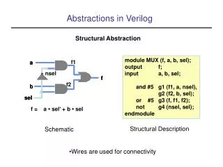
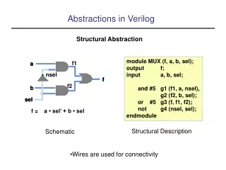
Delays inGate-Level Modeling • Delay are shown by # sign in all verilog modeling levels • Inertial rise delay • Inertial fall delay • Inertial turn-off delay and #(rise_val, fall_val, turnoff_val) a(out,in1, in2)
Delays inGate-Level Modeling (cont’d) • If no delay specified • Default value is zero • If only one value specified • It is used for all three delays • If two values specified • They refer respectively to rise and fall delays • Turn-off delay is the minimum of the two
Delays inGate-Level Modeling (cont’d) • Min/Typ/Max Values • Another level of delay control in Verilog • Each of rise/fall/turnoff delays can have min/typ/max values not #(min:typ:max, min:typ:max, min:typ:max) n(out,in) • Only one of Min/Typ/Max values can be used in the entire simulation run • It is specified at start of simulation, and depends to the simulator used • Typ delay is the default
Delays inDataflow Modeling Delaysin Verilog
Delays inDataflow Modeling • Regular Assignment Delays assign #delay out = in1 & in2; • As in Gate-Level Modeling the delay is output-inertial delay
Delays inDataflow Modeling (cont’d) • Implicit Continuous Assignment Delay wire #delay out = in1 & in2;
Delays inBehavioral Modeling Delaysin Verilog
Today Summary • Delays • Models • Inertial/Transport • Types • Rise/Fall/Turn-off • Min/Typ/Max Values • Delays in Verilog • Gate-Level Modeling • Dataflow Modeling • Behavioral Modeling