Download
1 / 18
180 likes | 309 Views
ALBA timing control. 21st Tango collaboration meeting May 13 and 14, 2009. Ramon Suñé Jairo Moldes Computing division ALBA. Index. Introduction Hardware Software TODO. Introduction.

E N D
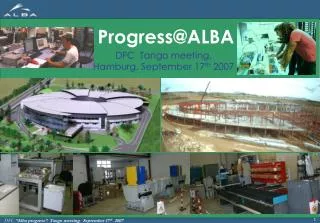
ALBA timing control 21st Tango collaboration meeting May 13 and 14, 2009. Ramon Suñé Jairo Moldes Computing division ALBA
Index Introduction Hardware Software TODO
Introduction The Event Generator receive the RF signal and produce the digital codes (events) that are sent over the same channel. The Fan Out modules distribute the events over the timing network. EVG RF input * All the events are transmitted sharing the same channel. The Event Stream Rate is synchronous with the RF frequency. Fan Out The Event Receivers decode the digital stream and will react to certain pre-programmed events producing an output. The characteristic of this output can be also pre-programmed. Fan Out Fan Out Fan Out EVR EVR EVR EVR EVR EVR EVR EVR EVR Output Output Output Output Output Output Output Output Output
Introduction Timestamp RF input (499.654MHz) EVR EVG 50 Hz The EVR will filter which events reach the EVG. Fan In Fan Out Fan In Fan Out Fan In Fan Out Fan In Fan Out Timestamp Timestamp Timestamp Timestamp Timestamp EVR EVR EVR EVR EVR EVR EVR EVR EVR Output Input Output Input Output Input Output Input Output Input Output Input Output Input Output Input Output
Introduction Final objective: make user's life easier Huge amount of output signals to configure and control (~800) Each signal may have different characteristics Allow the flexibility given by the hardware, but hide it's complexity Event based system EVG 1 unit Sends: 1 event / 8 bit distributed bus @ configurable clock rate (internal or external) EVRs 101 units Responds to events or dbus received generating an output signal Reacts on IN signals generating an event or as if an event was received Fanouts 32 units Hw components for distributing the optical signal upstream/downstream Minimal software control (enable/disable, status, clear flags, ...)
Hardware - EVG Event + DBus sent every 8.0053983356 ns = 1 / ( 499.654MHz / 4 ) Events: 8 bits code. 256 events (8 of them reserved) DBus: may transport a “signal” per bit or a byte of data Events sent on: Counter (internal / external) External signal in Upstream events: this will be used for Fast Interlock An event may be fired on raising AC mains voltage synchronization Software request 2 Events sequencer fired on: Counter Software
Hardware - EVRs • On event receiving, it is decoded and the associated actions are performed • Usual action: generate a pulse on one of the outputs • Other actions: • log event • save event on FIFO • forward downstream • heartbeat • 2 external hardware inputs that will (will be used for fast interlock): • generate an event to be treated internally as any other event, and/or • make the receiver send an event downstream (logically upstream)
Software What we have: Linux 2.6 driver for cPCI boards EVR-230, EVG-230 (C) EVG and EVR APIs from MRF slightly modified at ALBA to provide extra functions (C) Home made Fanout API (C++) EVG, EVR and Fanout C/C++ APIs translated to python Tango device servers for EVG, EVR and Fanout (python) GUI for EVG and EVR developed using PyQt TODO in the near future: Centralized timing device server and GUI Injection timing GUI
Software – EVG DS & GUI Distributed bus Events External inputs may fire: - Event - Distributed bus bit Events sequence Clock selection
Software – EVR DS & GUI Pulses configuration
Software – EVR DS & GUI Actions for event
Software – EVR DS & GUI - Outputs - External event - Backward event - Counters
TODO: Central timing DS Control over all channels on all receivers Global event clock configuration Global heartbeat application: Direct heartbeat Reverse heartbeat Global Timestamp: Configuration Data log recovery
TODO: Central timing GUI Access to all the central timing DS using a friendly tree like presentation
TODO: Injection timing GUI THALES PLCs