Download
1 / 6
60 likes | 126 Views
Status of MAPMT FEE Electronics. Boards Connector board – have 5 boards, 1 assembled

E N D
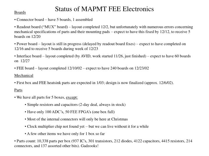
Status of MAPMT FEE Electronics • Boards • Connector board – have 5 boards, 1 assembled • Readout board (“MUX” board) – layout completed 12/2, but unfortunately with numerous errors concerning mechanical specifications of parts and their mounting pads – expect to have this fixed by 12/12, to receive 5 boards on 12/20 • Power board – layout is still in progress (delayed by readout board fixes) – expect to have completed on 12/16 and to receive 5 boards during week of 12/23 • Interface board – layout completed (by AVID, work started 11/26, just finished) – expect to have 60 boards on 12/27 • FEE board – layout completed 12/10/02 – expect to have 240 boards on 12/23/02 • Mechanical • First box and FEE heatsink parts are expected in 1/03; design is now finalized (approx. 12/6/02). • Parts • We have all parts for 5 boxes, except: • Simple resistors and capacitors (2-day deal, always in stock) • Have only 100 ADC’s, 50 FEE FPGA’s (one box full) • Most of the internal connectors will only be here at Christmas • Clock multiplier chip not found yet – but we can live without it for a while • A few other items we have only for 1 box so far • Parts count: 10,338 parts per box (937 IC's, 301 transistors, 212 diodes, 4122 capacitors, 4415 resistors, 214 connectors, and 137 assorted other bits). Gadzooks!
Status of MAPMT FEE Electronics • Summary of Specifications • Resolution: 12 bits (4096 LSB) (LSB a.k.a. “channel”) • 1/(Conversion gain): 6.909 fC/LSB (±1.5 % channel-channel variation, tempco ±100 ppm/K) • Pedestal (excluding contribution of offset current): 97.5 LSB (±10 LSB channel-channel variation, tempco ±0.3 LSB/K) • Offset current: ±100 nA (so ±1.1 LSB pedestal shift @ 75 ns) at 25 °C; tempco probably ±5 nA/K • Noise: 0.7 – 1.0 LSB (FEE noise only – does not include MAPMT gain fluctuations, etc.) • History effects: anticipate <10 LSB error for event preceeded by a long run of full-amplitude events (but this is hard to estimate... we must measure) • Flat-top integration window (to 0.1%): about 40 ns (reset interval will be set about 25 ns) • Crosstalk: <1% (probably will be much better) • No adjustments or trimming of the analog circuits – just build and test... • Latency buffer size: 170 cycles (17.5 s) • Test pulser: Each channel may be individually enabled or disabled to inject charge on the next subsequent pulser trigger command (which is received from the TCD). Pulser amplitude is set (calibrated to 5% accuracy) on the FEE board level, in common for all four channels. Pulser requires a pre-charge time of order 200 ms before each firing. (In particular, maximum rate is 4-5 Hz at best...) • Reset pulse skipping: Normal readout will use a reset of the integrator on each RHIC cycle. Reset skipping mode will reset only every Nth cycle. This is for diagnostic use (checking offset currents, for instance) and for use together with histogramming mode for gamma source calibration of the detector. • Fault-tolerant design allows defective FEE modules to be switched off with no ill effects on the others. FSR 27.6 pC