Download
1 / 4
40 likes | 113 Views
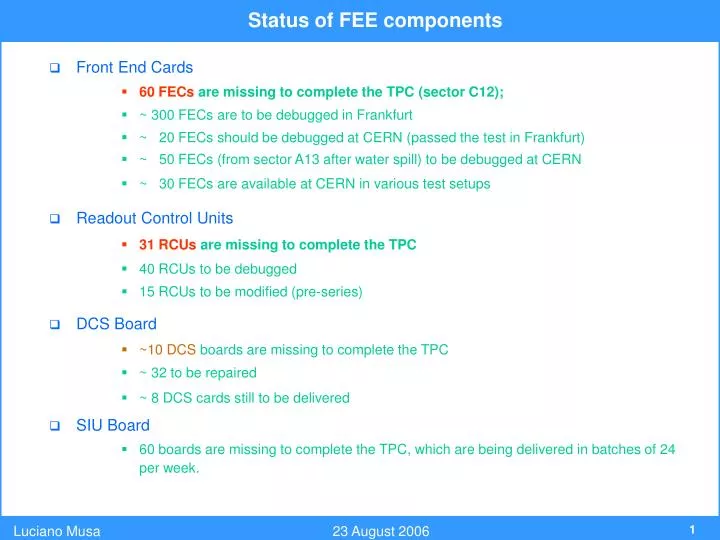
Status of FEE components. Front End Cards 60 FECs are missing to complete the TPC (sector C12); ~ 300 FECs are to be debugged in Frankfurt ~ 20 FECs should be debugged at CERN (passed the test in Frankfurt) ~ 50 FECs (from sector A13 after water spill) to be debugged at CERN

E N D
Status of FEE components • Front End Cards • 60 FECs are missing to complete the TPC (sector C12); • ~ 300 FECs are to be debugged in Frankfurt • ~ 20 FECs should be debugged at CERN (passed the test in Frankfurt) • ~ 50 FECs (from sector A13 after water spill) to be debugged at CERN • ~ 30 FECs are available at CERN in various test setups • Readout Control Units • 31 RCUsare missing to complete the TPC • 40 RCUs to be debugged • 15 RCUs to be modified (pre-series) • DCS Board • ~10 DCSboards are missing to complete the TPC • ~ 32 to be repaired • ~ 8 DCS cards still to be delivered • SIU Board • 60 boards are missing to complete the TPC, which are being delivered in batches of 24 per week.
Status of FE and RO Electronics Commissioning Front End Electronics Verification of the connection between FECs and ROC’s pad plane done during installation of the FECs by pulsing ROC’s cathode wires table with FEC identifier↔ Detector location correspondence list of pads that are not connected to the FECs Measurement of electronic gain, width, noise and baseline of all channels (all sectors) two sector at a time by pulsing ROC’s cathode wires database of gain, width, t0, pedestals, noise (5 values per channel) distributions of gain, pedestal and noise determine thresholds for zero suppression Global effects (characterization of few sectors) stability of pedestals (requires controlled cooling) characterization of the baseline oscillation induced by the gating grid (started) Measurement of temperature, voltages and currents of all FECs (all sectors) determination of the threshods for the generation of the interlock signal (turning off the FEC) (done only for 2 sectors) Characterization of temperature, voltages and currents (few sectors) different running conditions (power on, with and w/o cooling, high trigger rate, various ALTRO’s settings)
Commissioning objectives Readout Electronics and Back-end Systems FEE Configuration Creation of a set of basic Configuration Files (black events, zero suppression events, readout path test, etc.) FEE Command Coder Configuration of FEE via DCS development of the supervisory layer completion of the field layer (DCS board) application integration of field layer, intercom layer and supervisory layer Configuration of FEE via DDL FEE monitoring via DCS development of the supervisory layer completion and test of the intercom layer and field layer application TPC Data Monitor review and integration of the varous visual monitoring packages (MOOD, HLT, Expert Monitor, Offline) development of automated data quality monitor (what and where) Integration of FEE, ECS, DAQ, HLT, Trigger, Offline define standard run and calibration procedures and operations (in progress) verify procedures for detection and recovery from errors (e.g. illegal trigger sequence)
Summary of the tests performed on the A side • Test of all FECs, backplanes and RCUs • typical test period ~ 6hours • <0.8> FEC per sector had to be replaced (detailed analysis to be done) • common clock and synchronous trigger signals • typical trigger rate ~ few Hz • ~50k events acquired • 0.5% of events could not be reconstructed (to be investigated) • Trigger Crate (SBC, LTU, TTvi, TTCex) + TTCoc • NO circuit for the generation of the busy signal • Special Tests (not for all sectors) • trigger rate of 20Hz with 1000 samples / channel (64 MB / sec) • trigger rate of 500 Hz with 100 samples / channel (160 MB / sec) • trigger rate of 1KHz with 10 samples / channel (32 MB / sec) • Calibration Pulser Run with Zero suppression