Download
1 / 10
440 likes | 1.13k Views
COMMON EMITTER. Ritwik Chavhan Amit Singh Akram Khan. COMPONENTS. Transistor (BC 107) 1(One ) Resistors ( 1KOhm, 100KOhm) 1(One ) Bread board 1(One ). EQUIPMENT.

E N D
COMMON EMITTER RitwikChavhan Amit Singh Akram Khan
COMPONENTS • Transistor (BC 107) 1(One) • Resistors (1KOhm, 100KOhm) 1(One) • Bread board 1(One)
EQUIPMENT • Dual DC Regulated Power supply (0 - 30 V) • Digital Ammeters (0 - 200 mA, 0-200 A) • Digital Voltmeter (0 - 20V) • Connecting wires (Single Strand)
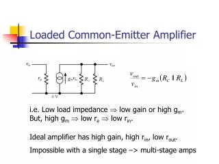
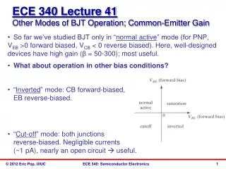
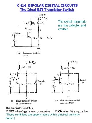
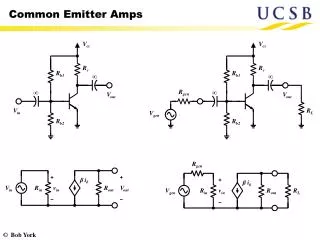
OPERATION • The input is applied between base and emitter, the output is taken between collector and emitter. Here emitter of the transistor is common to both input and output and hence the name Common Emitter Configuration. • Input characteristics are obtained between the input current and input voltage at constant output voltage. It is plotted between VBE and IB at constant VCE in CE configuration. • Output characteristics are obtained between the output voltage and output current at constant input current. It is plotted between VCE and IC at constant IB in CE configuration.
PROCEDURE • We connected the circuit as shown in the circuit diagram. • By keeping output voltage VCE = 0V ,we varied VCCupto 2V. • By varying VBB gradually, we can see changed value in base current IB and base-emitter voltage VBE.
Keeping emitter current IB = 20A by varying VBB. • Varying VCC gradually in steps of 1V up to 12V and note down collector current IC and Collector-Emitter Voltage(VCE).