Download
1 / 7
80 likes | 190 Views
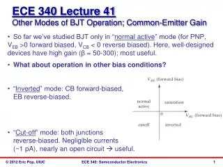
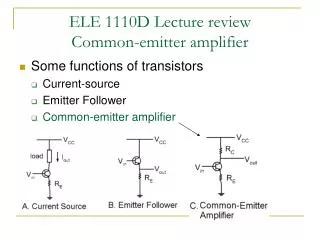
Common Emitter Analysis. VCC. RC. vc. IC. VB. VC. IB. VE. ve. IE. RE. vb. The DC setup is nearly the same as the emitter-follower, the only addition is the resistor RC. The Common Emitter Amplifier With Re. We will worry about a time Varying input voltage vb. VB is

E N D
VCC RC vc IC VB VC IB VE ve IE RE vb The DC setup is nearly the same as the emitter-follower, the only addition is the resistor RC. The Common Emitter Amplifier With Re We will worry about a time Varying input voltage vb. VB is supplied This will lead to a time varying Output signal, vc We will consider time varying effects: vb, ib, vc, ic, ve, ie
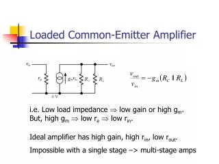
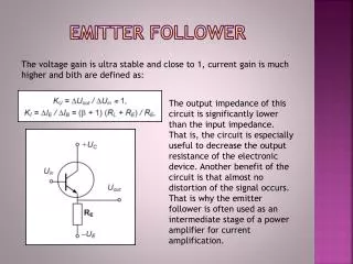
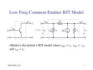
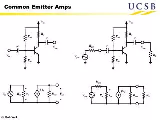
VCC RC vc IC VB VC VE ve IB vb IE RE How is VE related to VB? The Common Emitter Amplifier With Re VE = VB – (0.6 to 0.7) V ~ VB – 0.65 V How is VC related to VCC? VC = VCC – IC x RC How are I’s related? IE = IB + IC IC ~ b.IB IE ~ IC How are vb and ve related? ve = vb ie = ve/RE =vb/RE vb=ie.RE What is ic in terms of ie? vc = -ic Rc = -ie RC ic = ie vc/vb = -ieRC/ieRE = -RC/RE GAIN =
VCC RC vc IC VB VC VE IB vb IE ve RE Practical Considerations: The Common Emitter Amplifier With Re Resitance re into emitter RE looks like RE + re G = - RC/(RE+re) What is the lowest value of VE+ve? 0V so VB+vb-0.65>0 Transistor turns off, vc=0 How large can VB+vb get? Technically, to within 0.1V of VCC Practically, Gain*vb is within .1V of VCC What quiet value of VC maximizes the range for vc? VC = ½ VCC
VCC RC vc IC VB VC VE IB R1 vb b(RE+re) IE ve RE R2 What is the output Impedance? The Common Emitter Amplifier With Re RC || (resistance into collector) What is Resistance into collector? HINT: Current Source DV/DI = infinity Zout = RC Large Value What about input Impedance? Rin = (R1||R2||b(RE+re)) Controlled by R2
VCC IC C1 R? R1 VB VC VE IB IE b RE R2 R1 RE R2 C1 forms a High Pass Filter with R? Frequency Filtering with Capacitors: What is R? ? Through the base: b RE To Ground: R2 To VCC: R1 C1 R? = R1 || R2 || bRE Dominated by smallest of the three!
VCC IC C2 R? R1 C2 VB RL VC VE C1 IB IE R2 RE Frequency Filtering with Capacitors: C2 Forms a High Pass Filter with R? Just the Load, RL What is R? ? How small can RL be? RE || RL RL > RE