Download
1 / 67
730 likes | 863 Views
Module 1 Fundamentals of Crystal structure. Internal STRUCTURE for external strength. Materials. Non Crystalline. Crystalline. The properties of some materials are directly related to their crystal structures

E N D
Module 1Fundamentals of Crystal structure Internal STRUCTURE for external strength
Materials Non Crystalline Crystalline • The properties of some materials are directly related to their crystal structures • Solid materials may be classified according to the regularity with which atoms or ions are arranged with respect to one another • A crystalline material is one in which the atoms are situated in a repeating or periodic array over large atomic distances
CRYSTAL STRUCTURES upon solidification, the atoms will position themselves in a repetitive three-dimensional pattern, in which each atom is bonded to its nearest-neighbor atoms All metals, many ceramic materials, and certain polymers form crystalline structures under normal solidification conditions
Some of the properties of crystalline solids depend on the crystal structure of the material, the manner in which atoms, ions, or molecules are spatially arranged • When describing crystalline structures, atoms (or ions) are thought of as being solid spheres having well-defined diameters. This is termed the atomic hard sphere model in which spheres representing nearest-neighbor atoms touch one another Sometimes the term lattice is used in the context of crystal structures; in this sense ‘‘lattice’’ means a three-dimensional array of points coinciding with atom positions
UNIT CELLS • The atomic order in crystalline solids indicates that small groups of atoms form a • repetitive pattern • Thus, in describing crystal structures, it is often convenient to subdivide the structure into small repeat entities called unit cells • Unit cells for most crystal structures are parallelepipeds or prisms having three sets of parallel faces • A unit cell is chosen to represent the symmetry of the crystal structure • wherein all the atom positions in the crystal may be generated by translations of the unit cell integral distances along each of its edges • unit cell is the basic structural unit or building block of the crystal structure and defines the crystal structure by virtue of its geometry and the atom positions within
Metallic crystal structures • Three relatively simple crystal structures are found for most of the common metals: • Face-centered cubic • Body-centered cubic • Hexagonal close-packed.
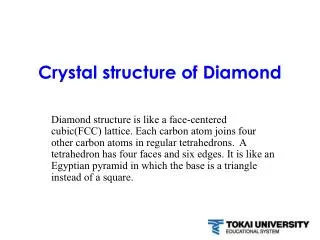
THE FACE-CENTERED CUBIC CRYSTAL STRUCTURE The crystal structure found for many metals has a unit cell of cubic geometry, with atoms located at each of the corners and the centers of all the cube faces. It is aptly called the face-centered cubic (FCC) crystal structure Example: copper, aluminum, silver, and gold c)aggregate of many atoms b) reduced-sphere unit cell (a) hard sphere unit cell
These spheres or ion cores touch one another across a face diagonal; the cube edge length a and the atomic radius R are related through • Each corner atom is shared among eight unit cells • Whereas a face-centered atom belongs to only two • Therefore, one eighth of each of the eight corner atoms and one half of each of the six face atoms, or a total of four whole atoms, may be assigned to a given unit cell
Coordination number For metals, each atom has the same number of nearest-neighbor or touching atoms, which is the coordination number. • For F C C, the coordination number is 12 • the front face atom has four corner nearest-neighbor atoms surrounding it • four face atoms that are in contact from behind • four other equivalent face atoms residing in the next unit cell to the front Atomic packing factor (APF) APF is the fraction of solid sphere volume in a unit cell, assuming the atomic hard sphere model For the FCC structure, the atomic packing factor is 0.74, which is the maximum packing possible for spheres all having the same diameter
THE BODY-CENTERED CUBIC CRYSTAL STRUCTURE Another common metallic crystal structure also has a cubic unit cell with atoms located at all eight corners and a single atom at the cube center. This is called a body-centered cubic (BCC) crystal structure (a) hard sphere unit cell b) reduced-sphere unit cell c)aggregate of many atoms
Center and corner atoms touch one another along cube diagonals, and unit cell length a and atomic radius R are related through • Two atoms are associated with each BCC unit cell • The coordination number for the BCC crystal structure is 8 • Also is the atomic packing factor for BCC is 0.68
THE HEXAGONAL CLOSE-PACKED CRYSTAL STRUCTURE • The top and bottom faces of the unit cell consist of six atoms that form regular hexagons and surround a single atom in the center • Another plane that provides three additional atoms to the unit cell is situated between the top and bottom planes • The atoms in this mid plane have as nearest neighbors atoms in both of the adjacent two planes • The equivalent of six atoms is contained in each unit cell • If a and c represent, respectively, the short and long unit cell dimensions the c/a ratio should be 1.633 • The coordination number and the atomic packing factor for the HCP crystal • structure are the same as for FCC: 12 and 0.74, respectively
DENSITY COMPUTATIONS—METALS where n number of atoms associated with each unit cell A atomic weight VC volume of the unit cell NA Avogadro’s number (6.023 X10²³atoms/mol)
crystalsystems (Unit cell geometry) • It is sometimes convenient to divide them into groups according to unit cell configurations and/or atomic arrangements • One such scheme is based on the unit cell geometry • that is, the shape of the appropriate unit cell parallelepiped without regard to the atomic positions in the cell
An x, y, z coordinate system is established • Origin at one of the unit cell corners • The unit cell geometry is completely defined in terms of six parameters • The three edge lengths a, b, and c, and • the three interaxial angles α,β and γ The cubic system, for which a= b= c and α=β=γ=90 has the greatest degree of symmetry Least symmetry is displayed by the triclinic system a ≠ b≠c, and α≠β≠γ
Crystallographic Points, Directions and Planes When dealing with crystalline materials, it often becomes necessary to specify some Particular point within a unit cell, a crystallographic direction or some crystal lographic plane of atoms Three numbers or indices are used to designate point locations, directions and planes The basis for determining index values is unit cell Consisting of three ( x, y and z) axes situated at one of the corners and coinciding with unit cell edges For some crystal systems—namely, hexagonal, rhombohedral, monoclinic, and triclinic— the three axes are not mutually perpendicular, as in the familiar Cartesian coordinate scheme
Point Coordinates: • The position of any point located within a unit cell may be specified in terms of its coordinates as fractional multiples of the unit cell edge lengths (i.e in terms of a, b and c) .
CRYSTALLOGRAPHIC DIRECTIONS A crystallographic direction is defined as a line between two points, or a vector. The following steps are utilized in the determination of the three directional indices • A vector of convenient length is positioned such that it passes through the origin of the coordinate system. • 2. The length of the vector projection on each of the three axes is determined; • these are measured in terms of the unit cell dimensions a, b, and c • 3. These three numbers are multiplied or divided by a common factor to • reduce them to the smallest integer values • 4. The three indices, not separated by commas, are enclosed in square brackets, thus: [uvw]. The u, v, and w integers correspond to the reduced projections along the x, y, and z axes, respectively
Exist both positive and negative coordinates • represented by a bar over the appropriate index • [111] direction would have a component in the - y direction • changing the signs of all indices produces an anti parallel direction The [100], [110], and [111] directions are common ones
For some crystal structures, several nonparallel directions with different indices are actually equivalent This means that the spacing of atoms along each direction is the same For example, in cubic crystals, all the directions represented by the following indices are equivalent: [100], [100], [010], [010], [001], and [001]. As a convenience, equivalent directions are grouped together into a family, which are enclosed in angle brackets, thus <100>. Furthermore, directions in cubic crystals having the same indices without regard to order or sign, for example, [123] and [213], are equivalent
HEXAGONAL CRYSTALS • A problem arises for crystals having hexagonal symmetry in that some crystallographic equivalent directions will not have the same set of indices • This is circumvented by utilizing a four-axis, or Miller–Bravais, coordinate system • The three a1 , a2 , and a3 axes are all contained within a single plane (called the basal plane), and at 120 angles to one another • The z axis is perpendicular to this basal plane • Directional indices, which are obtained as described above, will be denoted by four indices, as [uvtw] • By convention, the first three indices pertain to projections along the respective a1 , a2 , and a3 axes in the basal plane
Conversion from the three-index system to the four-index system Is accomplished by the following formulas where primed indices are associated with the three-index scheme and unprimed, with the new Miller–Bravais four-index system n is a factor that may be required to reduce u, v, t, and w to the smallest integers
CRYSTALLOGRAPHIC PLANES • The orientations of planes for a crystal structure are represented in a similar manner • The unit cell is the basis, with the three-axis coordinate system as represented • crystallographic planes are specified by three Miller indices as (hkl) • Any two planes parallel to each other are equivalent and have identical indices • The procedure employed in determination of the h, k, and l index numbers is as follows
If the plane passes through the selected origin, either another parallel plane must be constructed within the unit cell by an appropriate translation, or a new origin must be established at the corner of another unit cell • 2. At this point the crystallographic plane either intersects or parallels each of the three axes; the length of the planar intercept for each axis is determined in terms of the lattice parameters a, b, and c • 3. The reciprocals of these numbers are taken. A plane that parallels an axis may be considered to have an infinite intercept, and, therefore, a zero index • 4. If necessary, these three numbers are changed to the set of smallest integers by multiplication or division by a common factor • 5. Finally, the integer indices, not separated by commas, are enclosed within • parentheses, thus: (hkl)
Methodology to define crystallographic planes in cubic crystal: • determine the intercepts of the plane along the crystallographic axes, in terms of unit cell dimensions. If plane is passing through origin, there is a need to construct a plane parallel to original plane. • take the reciprocals of these intercept numbers. • clear fractions. • reduce to set of smallest integers. • - The three indices are enclosed in parenthesis, (hkl). A family of planes is represented by {hkl}
An intercept on the negative side of the origin is indicated by a bar or minus sign positioned over the appropriate index. Furthermore, reversing the directions of all indices specifies another plane parallel to, on the opposite side of and equidistant from, the origin
Determine the Miller indices for the plane shown in the accompanying sketch
Since the plane passes through the selected origin O, a new origin must be • chosen at the corner of an adjacent unit cell, taken as O’ The y and z axes intersections, referenced to the new origin O’, are -b and c/2, respectively Thus, in terms of the lattice parameters a, b, and c, these intersections are 0, -1, and 2 The reciprocals of these numbers are since all are integers, no further reduction is necessary Finally, enclosure in parentheses yields
A plane is indicated by lines representing its intersections with the planes that constitute the faces of the unit cell or their extensions
The indices are removed from the parentheses • Reciprocals are taken This means that the particular plane parallels the x axis while intersecting the y and z axes at b and c, respectively
ATOMIC ARRANGEMENTS The atomic arrangement for a crystallographic plane, which is often of interest, depends on the crystal structure. The (110) atomic planes for FCC and BCC crystal structures are represented below (a)Reducedsphere FCC unit cell with (110) plane. (b) Atomic packing of an FCC (110) plane
Reduced-sphere BCC unit cell with (110) plane. (b) Atomic packing of a BCC (110) plane
HEXAGONAL CRYSTALS For crystals having hexagonal symmetry, it is desirable that equivalent planes have the same indices; as with directions, this is accomplished by the Miller–Bravais This convention leads to the four-index (hkil) scheme, which is favored in most instances, since it more clearly identifies the orientation of a plane in a hexagonal crystal. There is some redundancy in that i is determined by the sum of h and k through
CLOSE-PACKED CRYSTAL STRUCTURES METALS It may be remembered from the discussion on metallic crystal structures that both face-centered cubic and hexagonal close-packed crystal structures have atomic packing factors of 0.74, which is the most efficient packing of equalized spheres or atoms
In addition to unit cell representations These two crystal structures may be described in terms of close-packed planes of atoms Both crystal structures may be generated by the stacking of these close-packed planes on top of one another; the difference between the two structures lies in the stacking sequence. Let the centers of all the atoms in one close-packed plane be labeled A Associated with this plane are two sets of equivalent triangular depressions formed by three adjacent atoms, into which the next close-packed plane of atoms may rest
Those having the triangle vertex pointing up are arbitrarily designated as Bpositions, while the remaining depressions are those with the down vertices, which are marked C A second close-packed plane may be positioned with the centers of its atoms over either B or C sites; at this point both are equivalent Suppose that the B positions are arbitrarily chosen; the stacking sequence is termed AB The real distinction between FCC and HCP lies in where the third close-packed layer is positioned
For HCP, the centers of this layer are aligned directly above the original A positions. This stacking sequence, ABABAB . . . , is repeated over and over Of course, the ACACAC . . . arrangement would be equivalent These close-packed planes for HCP are (0001)-type planes
For the face-centered crystal structure, the centers of the third plane are situated over the C sites of the first plane This yields an ABCABCABC . . . stacking sequence; that is, the atomic alignment repeats every third plane.
CRYSTALLINE AND NONCRYSTAL L INE MATERI ALS Single Crystal For a crystalline solid, when the periodic and repeated arrangement of atoms is perfect or extends throughout the entirety of the specimen without interruption, the result is a single crystal All unit cells interlock in the same way and have the same orientation. Single crystals exist in nature, but they may also be produced artificially. They are ordinarily difficult to grow, because the environment must be carefully controlled.
Imperfections in Solids • The properties of some materials are profoundly influenced by the presence of imperfections. • Consequently, it is important to have a knowledge about the types of imperfections that exist, and the roles they play in affecting the behavior of materials. • For a crystalline solid we have tacitly assumed that perfect order exists throughout the material on an atomic scale • However, such an idealized solid does not exist; all contain large numbers of various defects or imperfections.
As a matter of fact, many of the properties of materials are profoundly sensitive to deviations from crystalline perfection; • The influence is not always adverse, and often specific characteristics • are deliberately fashioned by the introduction of controlled amounts or • numbers of particular defects • crystalline defect’’ is meant a lattice irregularity having one or more of its dimensions on the order of an atomic diameter
Types of Imperfections • Thermal vibrations • Point defects • a) Vacancies • b) interstitial. • 3. Line defects • a) Edge dislocation • b)Screw dislocation • 4. Surface defects (Interfacial defects) • a) Grain boundaries • b) Twin boundaries • 5. Volume defects