Download
1 / 24
250 likes | 387 Views
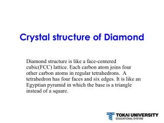
Crystal Structure. A “ unit cell ” is a subdivision of the lattice that has all the geometric characteristics of the total crystal. The simplest choice of this repeating combination of the atoms on a set of lattice points is called the unit cell.

E N D
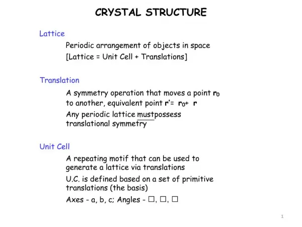
Crystal Structure • A “unit cell” is a subdivision of the lattice that has all the geometric characteristics of the total crystal. • The simplest choice of this repeating combination of the atoms on a set of lattice points is called the unit cell. • All unit cells in a perfect crystalline solid are identical so if we describe one unit cell then we have described them all.
Lattice Parameters • The lattice parameters describe the size and shape of the unit cell. • There are three lengths, a, b, and c that describe the cell’s edges. • There are three angles, alpha, beta, and gamma, that describe the three angles between the adjacent cell axes. Lattice parameters and their use to describe crystal systems.
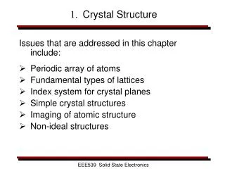
The Seven Crystal Systems • There are only seven unique Crystal Systems, i.e., • 1. Cubic 2. Tetragonal 3.Orthorhombic 4. Rhombohedral • 5. Hexagonal 6. Monoclinic 7. Triclinic
Bravais Lattice Systems • There are 14 types of unit cells or Bravais lattices that are grouped into the 7 crystal systems (see next slide). • There are four basic types of unit cells: • Simple • Body-centered • Face-centered • Base-centered • These lattices are the skeletons of solids upon which the crystal structures of atoms are built
The fourteen types of Bravais lattices grouped into the seven crystal systems.
Atoms in unit cells tend to stack as close as possible such that the outer shells of electrons just touch the adjacent atom’s. • This type of stacking is called the “Hard Sphere” model of simple crystal structures. • There is a relationship between the atomic radius of the atoms and the lattice parameters in such unit cells. • These relationships are easy to calculate. • Note that the BCC is from corner to opposite corner, ie., Nearest Neighbour Distances Heads up: dislocations.
Atom Positions/Coordinates • Atoms positions/coordinates in a unit cell use the x, y, z axes where, • the + x axis is coming out of the page • the + y axis is in the direction to the right of the paper • the + z axis is pointing to the top of the paper • Any lattice point can be designated this way. • The point is indicated by three integers or fractions separated by commas and enclosed by parenthesis such as (1,0,0). • Nomenclature is important as we will see other rules to describe directions and planes in crystals.
Certain directions in the unit cell are of particular importance. For example, metals deform in directions along which atoms are in closest contact. • The directions are called Miller Indices. • The procedure for finding Miller Indices is as follows: • 1. Using the right-handed coordinate system, determine the coordinates of two points that lie on the direction. • 2. Subtract the coordinates of the “tail” point from the coordinates of the “head” point to obtain the number of lattice parameters traveled in the direction of each axis of the coordinate system. • 3. Clear any fractions that may result and/or reduce the results obtained from the subtraction to the lowest integers. • 4. Enclose the numbers in square brackets [ ]. If a negative sign is produced, represent the negative sign with a bar over the number. Directions in the Unit Cell
Directions in the Unit Cell • Determine the Miller indices of directions A, B, and C in the figure below. • Direction A • 1. Two points are 1,0,0 and 0,0,0 • 2. 1,0,0 – 0,0,0 = 1,0,0 • 3. No fractions to clear or integers to reduce • 4. [100] is the answer. • Direction B • 1. Two points are 1,1,1 and 0,0,0 • 2. 1,1,1 – 0,0,0 = 1,1,1 • 3. No fractions to clear or integers to reduce • 4. [111] is the answer • Direction C • 1. Two points are 0,0,1 and ½,1,0 • 2. 0,0,1 – ½,1,0 = -1/2, -1,1 • 3. 2(-1/2,-1,1) = -1,-2,2 • 4. is the answer • How do we say a negative direction?
Several points to remember about Miller indices include the following: • Because the directions are vectors, a direction and its negative are not identical, i.e., [100] is not equivalent to as they represent the same line but opposite directions. • A direction and its multiple are identical, i.e., [100] is the same as [200]. It was just not reduced to its lowest integer. • Certain groups of directions are equivalent, i.e., they have their particular indices because of the way we constructed the coordinates. For example, [100] is equivalent to [010] so we write these equivalent indices as < > and we call them directions of a “form”.Would we expect a material to have the same properties in each of these directions? Directions in the Unit Cell
Planes in a Unit Cell • “Miller Indices” are also used for atomic planes in crystals. • The Miller indices of an atomic plane are defined as the reciprocals of the fractional intercepts that the plane makes with the crystallographic x, y, z axes of the three non-parallel edges of the cubic unit cell.
Procedure for determining the nomenclature of planes: • Choose a plane which DOES NOT pass through the origin! • Determine the intercepts of the plane in terms of the crystallographic x, y, z axes for a unit cube. These intercepts may be fractions. • Form the reciprocals of these intercepts. • Clear the fractions and determine the smallest set of whole numbers that are in the same ratio as the intercepts. These whole numbers are the Miller indices of the crystallographic plane and are enclosed in round parentheses without the use of commas. • The notation (hkl) is used to indicate Miller indices of planes in a general sense, where h, k, and l are the Miller indices of a crystal plane for the x, y, and z axes, respectively. • Note that negative numbers should be written with a bar over the number. Planes in a Unit Cell
Planes in the Unit Cell Determine the Miller indices of planes A, B, and C in the figure below. • Plane A • 1. x = 1, y = 1, z = 1 • 2. 1/x = 1, 1/y = 1, 1/z = 1 • 3. No fractions to clear or integers to reduce • 4. (111) is the answer. • Plane B • 1. x = 1, y = 2, z = infinity • 2. 1/x = 1, 1/y = 1/2, 1/z = 0 • 3. clear fractions: 1/x = 2, 1/y = 1, 1/z = 0 • 4. (210) is the answer • Plane C – we must move the origin since it passes through 0,0,0. We’ll move it one lattice parameter in the negative y-direction. Then, • 1. x = infinity, y = -1, z = infinity • 2. 1/x = 0, 1/y = -1, 1/z = 0 • 3. No fractions to clear or integers to reduce • 4. or is the answer
Planes in a Unit Cell • Several characteristics of Miller indices of planes are worth noting. • Planes and their negatives are identical. • Planes and their multiples are not identical, e.g., (111) ≠ (222). • In each unit cell, “planes of a form” represent equivalent planes that have their particular indices because of the orientation of the coordinates. • They are represented by { }. • For example, {110} = (110), (101), (011), • In cubic crystal systems, a direction that has the same indices as a plane is perpendicular to that plane. (Show example on board)
Close-Packed Planes and Directions for FCC • For FCC crystals, the {111} planes are close-packed, which is more easily seen by observing the lines passing through the face-centered atoms, which make up the {111} planes as seen below.
(110) (111) FCC BCC <110> <111> Relationship between the (111) FCC and the (110) BCC Kurjumov-Sachs relationship
Number Of Atoms/Unit Cell • A specific number of lattice points define each of the unit cells. • For example, the corners, the body-centered and face-centered points are easily identified. • When counting the number of lattice points, we must recognize that they can be shared by more than one unit cell (see below).
This is the number of atoms touching a particular atom or the number of nearest neighbors for that particular atom. • It is an indication of how tightly and efficiently the atoms are packed together. • For ionic solids, the coordination number is the number of nearest ions. • We can see below that the Simple Cubic (SC) and Body Centered Cubic (BCC) have a coordination number of 6 and 8, respectively. Coordination Number The coordination of atoms in the a) SC and b) BBC unit cells.
Packing Factor • This is the fraction of space occupied by atoms, assuming that the atoms are hard spheres. • The general expression for the packing factor is: • For a FCC cell, there are four lattice points per cell. If there is 4 atoms per lattice point then there are 4 atoms/cell. The packing factor for FCC can be written as: • This is the most efficient packing possible for the ideal crystal structure. Higher packing is possible for non-ideal structures. • BCC cells have a packing of 0.68 • SC cells have a packing of 0.52 • HCP also has a packing of 0.74
When the close-packed planes of an atomic structure such as SC, BCC, FCC and HCP are considered, the planes within the unit cell can be put together to have a repetition of their “Stacking Sequence”. • The close-packed planes of FCC are the {111} and there are 3 separate planes making up the unit cell which gives the FCC structure a stacking sequence of ABCABCABC … . Stacking Sequence 111 planes FCC
Close-Packed Planes and Directions • A summary of the close-packed planes and directions for cubic and hcp structures is given below.