Download
1 / 50
520 likes | 693 Views
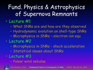
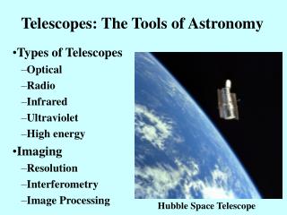
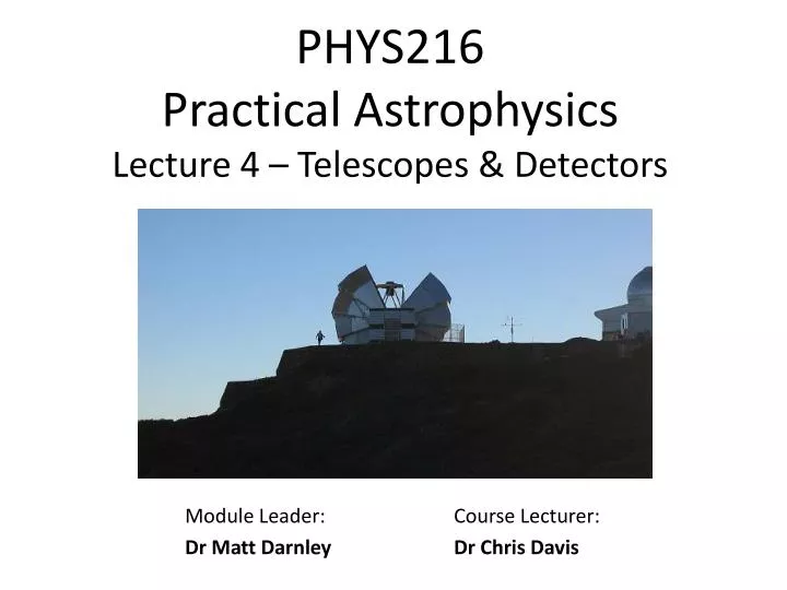
PHYS216 Practical Astrophysics Lecture 4 – Telescopes & Detectors. Module Leader: Dr Matt Darnley. Course Lecturer : Dr Chris Davis. Wavelength Coverage.

E N D
PHYS216 Practical AstrophysicsLecture 4 – Telescopes & Detectors Module Leader: Dr Matt Darnley Course Lecturer: Dr Chris Davis
Wavelength Coverage No telescope yet conceived can detect photons with wavelengths covering the entire EM spectrum. For example the physics of detecting (or intercepting) very high energy photons (gamma, X-rays) is fundamentally different from the physics of detecting low energy radio waves, or even optical photons. This problem is somewhat amplified by the Earth's atmosphere which does a very good job of absorbing IR and high energy photons (although this has a good side from a biological/life on Earth point of view).
UV IR
Radio, l ≈ 1 m Giant ground-based dishes with electronic receivers. (Left) The 100-m Green Bank Radio Telescope (GBT), NRAO Green Bank, West Virginia. (Right) Artists' impression of part of the Square Kilometer Array (SKA).
Sub-millimetre, l ≈ 1 mm Dishes on high mountains (or in space) to get above water vapour which absorbs most of the photons. (Left) The 15-m James Clerk Maxwell Telescope (JCMT), Mauna Kea, Hawaii. (Right) The 3.5m Herschel Space Observatory (artists impression).
Mid- to Far-Infrared, l ≈ 0.01-0.1 mm Satellites or aeroplanes with very cold electronic detectors. (Left) The 0.85-m Spitzer Space Telescope. (Right) The Stratospheric Observatory for Infrared Astronomy (SOPHIA) and its 2.5m telescope.
SOFIA – IR Astronomy from a Plane! http://www.sofia.usra.edu/
SOFIA Super-TIGER Astronomy from a Plane! • Quick, low cost (few million $) access to high altitudes EBEX BLAST
Near-Infrared, l ≈ 1-5 mm Telescopes on high mountains with cold electronic detectors. (Left) The 3.8m UK Infrared Telescope (UKIRT), Hawaii. (Right) Model of the James Webb Space Telescope (JWST, optical to mid-IR).
JWST Deployment at L2i.e. when its 1.5 million km from Earth
Optical, l ≈ 0.4-0.8 mm Telescopes, preferably on high mountains, with electronic or photographic detectors. (Left) The four 8.2-m telescopes of the Very Large Telescope (VLT), Chile. (Right) The 2-m fully robotic Liverpool Telescope (LT), La Palma.
Utraviolet, l ≈ 0.1 mm Satellites with electronic detectors. (Left) The 0.5m Galaxy Evolution Explorer (GALEX). (Right) The 2.4m Hubble Space Telescope (HST, UV to near-IR).
X-ray, l ≈ 10 nm Satellites with grazing-incidence mirrors and electronic detectors. (Left) The X-ray Multi-Mirror Mission (XMM) Newton Telescope. (Right) The Chandra X-ray Observatory,
Gamma-ray, l ≤ 1 nm Satellites with collimators and electronic detectors. (Left) The Fermi Gamma-ray Space Telescope. (Right) Swift (Gamma-ray, X-ray, UV and optical).
High-energy and Far-IRastronomy from Balloons! BLAST (left) and EBEX (above) both observe in the Far-IR. Many balloons are launched from Antarctica, where water vapour levels are very low…
Why use telescopes? • Light collection power - Think about the flux intercepted by the eye (a few millimetres in diameter) and the largest ground based optical telescopes (some over 10m in effective diameter). • Integration - Integrations of many hours are possible using ground based telescopes, even days or weeks for space based ones. However, the eye has a sampling frequency of around 25Hz (although this itself is a vast area of research and not so straight forward). • Resolving power - The eye is rarely seeing-limited; due to its small aperture the eye is almost exclusively diffraction-limited, giving very low resolution.
Diffraction-limited vs. Seeing-limited There is a fundamental maximum to theresolution of any optical system (telescope, microscope, your eye!) which is due to diffraction. An optical system with the ability to produce images with an angular resolution (the angular separation between two objects, or the “width” of a star measured at half the intensity) that is as good as the instrument's theoretical limit is said to be diffraction limited. However, most telescopes are seeing limited – which means the atmospheric conditions dictate the resolution of the observation.
The Rayleigh (or Diffraction) Limit The angular resolution of an optical system, q , can be estimated using the Rayleigh criterion, which relates the size of the aperture, D (e.g. the diameter of the telescope primary mirror) and the wavelength of the observation, l(550 nm, say, for the optical) to q : sin q = 1.22 l/ D. The Gemini Telescope has an 8 meter diameter mirror, and it operates in the optical (550 nm) and the infrared (5 mm) At which wavelength would you expect to get better spatial resolution? Image: VikDhillon The Hubble Space Telescope has only a 2.4 m aperture (primary mirror). What’s the best resolution you can expect from HST in the optical, and Gemini?
What affects the “Seeing” The blurring or twinkling of stars by the atmosphere is referred to as Seeing. As light rays enter the denser atmosphere from the vacuum of space they are refracted. Variations in the density, due to temperature gradients or turbulence, cause the refraction to alter as the light passes through the air… Understanding atmospheric physics can ultimately affect where you build your telescope!
Magnification & Field-of-View Magnifying power = Focal length of objective, fo Focal length of eyepiece, fe Focal ratio ofobjective (or mirror) = Focal length of lens, fo Diameter of lens, D The focal ratio is indicative of the maximum field-of-view available through the telescope system (primary/secondary mirror); lower f-ratios give larger f-o-v.
Magnification & Field-of-View The f-ratio of the Liverpool Telescope primary mirror is f/3. Primary diameter, D = 2.0 m. Therefore, the mirror focuses light to a point 6 m above the primary. However…. the secondary mirror changes the overall f-ratioof the telescope! The effective f-ratio of the LT is f/10 Therefore, the focal length is ≈ 20 m That’s the distance from the primary mirror, up to the secondary, and back down to the cassegrain where the instruments are mounted.
Magnification • Unfortunately a small fuzzy blob when magnified just becomes a large fuzzy blob (remember seeing?)! Magnified objects are also fainter, since you spread the light out over more pixels on your detector. • Magnification is not always the primary need when selecting a telescopes for astronomical research.
Reflectors vs Refractors The first astronomical telescopes, such as those designed by Galileo, used lenses and are therefore called refractors. Refractors - Pros: • Rugged - optical alignment not subject to much disturbance after initial setting up. • Inner glass surfaces sealed in, so rarely need cleaning. • Air current and temperature effects minimised due to enclosed tube. Refractors - Cons: • Lenses must be supported around the edge. • Larger lenses are very heavy, therefore making them very expensive. • Various forms of aberration.
Aberrations • Spherical aberration - A spherically shaped lens will produce a curved focal plane with blurred off-axis images. In the example below, the further the rays are from the optical axis, the closer to the lens they cross the axis when focused.
Aberrations • Coma (left) and Astigmatism (right) - Off-axis images further distorted. Coma refers to the “comet-like” appearance of images suffering from Coma. Coma: Rays parallel with the optical axis are focused to a point, those not parallel with the axis are spread out… Astigmatism: Rays in perpendicular planes have different focii
Aberrations • Chromatic aberration - Refractive index in a lens is a function of wavelength (see lab section of the course). Different foci for different wavelengths give rise to distorted colour “halos" around stars (nb. refractive index is wavelength-dependent). A long focal length (thin lenses) helps reduce this problem, as do compound lenses made of different materials.
Aberrations Instrument designers produce “spot diagrams" with ray-tracing software to determine how distorted images will be. The aim is to make the effects of distortion negligible compared to the intrinsic image quality (e.g. seeing). Spot diagrams for the Subaru/CISCO instrument, at different wavelengths and off-axis angles. Aberrations can to some degree be reduced by using multiple-lens systems.
HST Spherical Aberrations The 2.4m primary mirror on-board the Hubble Space Telescope was, at the time, the most precisely ground mirror ever produced. Unfortunately it had been precisely ground to the wrong shape. This introduced a catastrophic spherical aberration into the optical system. As it was considered infeasible to return the telescope to Earth and replace/re-grind the mirror, the problem was corrected three years after launch by introducing additional correcting optics during the first servicing mission. (Left) WFPC1 image of M100 before corrective optics. (Right) WFPC2 image of M100 after corrective optics.
Reflectors vs. Refractors • Most modern astronomical telescopes: • Reflectors • The largest single-piece optical telescope in the world is currently the Large Binocular Telescope : 2x 8.4 m mirrors. • Segmented mirrors (see e.g. the Keck mirror below-left) arethe future..? • Reflectors - Pros: • No chromatic aberration. • By using paraboloidal shapes, spherical aberration can be removed. • Easier to manufacture • Can be supported from behind • Reflectors – Cons: • Open to the elements • Coma and astigmatism still a problem Above - LBT 8.4m mirror. Below – Keck 10m mirror
Reflectors Most large telescopes are reflectors (though their instruments may still use lenses) Naysmith Focus Instruments are usually mounted at the Cassegrain, Prime or Naysmith Focus Gemini 8 meter Telescope
Telescope Mountings - Equatorial There are two main types of telescope mounting: Equatorial and Altitude-Azimuth (Alt-Az). • Equatorial telescopes: • Must be set-up/designed for a particular latitude, such that the declination axis points directly to the north (or south) pole. • Only needs to track stars through one axis. • Simple design, but heavy. • Object tracking is straight forward; the telescope only needs to track in RA (along one axis); Dec is fixed! Model of the UK Infrared Telescope. The red “tube” is an instrument sitting on the primary mirror!
Telescope Mountings – Alt-Az Two main types of telescope mounting: Equatorial and Altitude-Azimuth. • Alt-Az telescopes: • Simple “up-down" and “revolving" mount. • Must track through both the Alt and Az axis, PLUS Cassegrain de-rotation. • Tracking can be tricky • Zenith “blind spot" due to near-infinite de-rotator speeds. • Simple engineering • Used on most modern large telescopes. Computer model of the proposed Thirty Meter Telescope (TMT)
Detectors – the Basics Methods of detection of light are very different for different wavelengths. Here we will only consider optical detectors. One good measure of the quality of a detector is its efficiency at detecting photons. This is known as the quantum efficiency (QE). QE is defined as the probability that a photon with a given energy (i.e. at a specific wavelength) will be detected. So if only 1 in 10 photons are detected, the QE is 10%. A detector with a QE of 40% will need twice the exposure time of a detector with a QE of 80% to collect the same number of photons. In general, the QE of a detector is a function of wavelength and hence modern detectors are often designed specifically for a particular wavelength regime.
The Eye There are 2 types of detectors (retinal receptor cells) in the eye, rods and cones Rods - detect monochrome only - they contain rhodopsin, a complex protein pigment in layers 20 nm thick. When a photon is absorbed, a piece of the protein breaks off leaving behind a colourless substance (opsin). An associated change in potential causes an electrical signal in the optic nerve. Peak sensitivity of rods occurs at wavelengths around 500 nm (for obvious reasons!). Rhodopsin regenerates slowly (see below). Cones - come in 3 types and are sensitive to 3 distinct wavelength ranges which the eye interprets as blue (narrow, with a peak near 419 nm), green (broader, with a peak near 531 nm) and red (also broad, with a peak near 558 nm, which is actually more like yellow).
Dark Adaptation Wavelengths shorter than 315 nm (UV) are absorbed by the cornea (potentially causing injury) and do not reach the retina. Retinal sensitivity sometimes extends (with very low sensitivity) to 1000 to 1050 nm (into the near-IR). Note that if your eyes were sensitive to much longer wavelengths you would look through a sort of `infrared fog', since you would see heat energy everywhere. In the dark, rods dominate since their sensitivity is about 100 times greater than for cones - hence at night we rely on monochrome vision. In the dark, rhodopsin gradually reforms on a time-scale of 30 mins. Red light is much less likely to reduce dark adaption (hence red lights are often used in `dark' rooms, and red torch filters are used on observing trips!).
Naked Eye Astronomy The Rayleigh limit* of the fully open iris (5-7mm) is ≈25” but the receptor cell spacing is much coarser: 1’-2’ is therefore the max resolution you can expect from your eye. The eye's response to light intensity is logarithmic: this is the origin of the magnitude scale. The faintest stars which are naked eye visible on a moonless night have mV≈ 6. • Q. Can you resolve (distinguish) Maia from Alcyone with the naked eye? • Maia (V = 3.9m) • RA: 3h45m 50.0sDec: 24o 22’ 10” • Alcyone (V = 2.9m) • RA: 3h 47m 29.0s Dec: 24o 06’20” David Malin/AAT *The angular resolution, q , can be estimated using the Rayleigh criterion, which relates the size of the aperture, D and wavelength of the observation, l,to q : sin q = 1.22 l/ D.
Photographic Plates • Photons cause chemical changes in photographic emulsions. The use of hypersensitizing can increase the QE to 10%. • Limitations: Non-linear response. Scattering degrades resolution. • Advantages: Large area and relatively cheap. • Scanning machines have been used extensively to digitize photographic plates, e.g. the Digitised Sky Survey Catalogue – still widely used by Astronomers! Photo courtesy ESO The DSS largely contains scanned photographic plates obtained at the Palomar Observatory (North) and the UK Schmidt Telescope (South)
Photographic Plates Left: Hubble at the Palomar Schmidt; Right: His 1926 plate of M33 with at least one Classical Nova marked While once widely (even exclusively) used by professional astronomers, now only a hand-full of amateurs still regularly use plates. However, vast archives of almost a century of plate observations still exist and are still frequently referred to.
CCDs (Charge-Coupled Devices) Photons incident on a semiconductor (usually doped silicon) produce electron-hole pairs (below-left). The electrons are trapped in potential wells produced by attached electrodes, and accumulate until read out by charge coupling the electrodes. By cycling the voltages on each electrode in sequence, we can shuffle the charge along to an output electrode (below-right). This process is known as charge coupling. The resulting analogue signal is amplified and digitised. Note: IR photons with l > 1.1 mm don’t have enough energy to create a free electron! Electrons collect in potential wells produced by the gate electrodes (G); charge is shifted to the right by shifting the applied voltage on each gate. An amplifier at the end of the row converts the charge to a voltage… Above: a photon with sufficient energy excites an electron from the valence to the conduction band, thereby producing an electron-hole pair.
CCDs (Charge-Coupled Devices) CCDs are of course now commonly used in digital cameras. They were adopted for use by astronomers in the mid-1980s because of their much greater efficiency and sensitivity compared to photographic film. Whilst CCDs are commonly used in every-day items, “science grade” optical CCDs are still extremely expensive, and IR detectors (strictly-speaking, these are not CCDs, since they don’t shuffle charge) can be a factor of ten times more expensive again. (Left) The array of four 2kx4k pixel detectors of the INT WFC (plus the finder chip). (Right) WFC3 being installed on-board the HST, the camera contains two 2kx4k pixel detectors and a single 1kx1k detector. Note the size of the camera compared to the detectors.
CCDs – Quantum Efficiency Efficiency of conversion of photons into electrons - the Quantum Efficiency - in the CCD material is around 75-90% (cf 2% for photographic lm). However, QE does change with wavelength and temperature, and even depending on whether the “front or back” of the CCD is illuminated! Standard optical CCDs are typically sensitive to radiation in the wavelength range l= 400 - 1000 nm. LEFT: The QE response of the detectors used in the Andor cameras at the LT when cooled to -100oC. Note how QE drops off sharply in the UV (photons reflected) and near-IR (photons pass through the device). Photons falling onto the “front” of the detector must traverse the gate electrodes (see two slides back); the gate electrodes can reflect or absorb photons, thereby reducing the QE. It may therefore be desirable to illuminate the back of the CCD.
CCDs - Cryogenics Scientific grade CCDs (e.g. those used on telescopes) need to be cooled. Expansion of with liquid Nitrogen (T~70K) or even liquid Helium (T~ 4K) can be used. The CCD is mounted insidein a cryostat or dewar. Cooling reduces noise associated with “dark current” - signal associated with thermal excitation of electrons in the semiconductor material. The associated noise is proportional to √dark current (see next section). Closed-cycle means that the fluid (liquid or gas) that exchanges the heat is kept within a closed circuit. RIGHT: The IO:O cryostat – the gold cylinder - mounted on the bottom (the cassegrain focus) of the Liverpool Telescope. So how does a CCC work? Remember those laws of Thermodynamics!? PV = nRT ??
CCDs - Cryogenics This is the layout of the Closed-Cycle Cooling system being used at the LT to cool the detectors in IO and FRODOspec. CryoTiger Compressor RETURN (30 psi) Air flow Cold Head on the instrument Heat Exchanger Gas Compressor SUPPLY (300 psi) Gate valve to vacuum pump The Cryotiger pumps compressed PT13 liquid into the cold-head on the instrument, where it expands adiabatically, thereby extracting heat from the copper heat strap. “Warm” PT13 gas returns to the cryotiger, where it is passes through the compressor and heat exchanger, before again being pumped back through the cold-head. Note that everything inside the coldhead is kept in a vacuum, and the heat shield protects the cold internals from radiative heating from the outer jacket. Heat Shield Cold Plate Getter Copper heat strap
CCDs - Cryogenics “Amateur" astronomical CCD cameras - such as those used in your labs and during the field trip - use thermo-electric cooling, via the Peltier effect, to cool the detectors by typically20 – 30o below the ambient temperature. The Peltier effect uses Thermo-electric cooling (conversion of temperature differences to voltage) to extract heat energy from the system. Usually a hot and cold plate are connected by doped semi-conductive thermo-couples. When a DC voltage is applied across the device (note the +ve and –ve terminals) the hot plate heats up and the cold plate cools down… The device effectively transfers heat from one side to the other. Advantages of this cooling device: lack of moving parts (reliable, low maintenance) and does not involve cryogenic liquids (like PT13 or N2). Note: in the Peltier effect, heat is transferred from one material to another as electrons flow to an environment with higher energy, E, but also higher entropy, S, and therefore lower free energy (F = E-ST)
CCDs – Gain & Bias GAIN: In an ideal world, the number of “counts" recorded in a particular pixel in the image from a CCD camera would be equal to the number of photons detected. However the electronics that lie between the CCD camera and the resultant image can slightly complicate matters. When designing the electronics (the Analogue-to-Digital converter, or ADC) one must decide upon the length of numbers used, typically 16-bit unsigned integers (giving a range from 0 [216 – 1] or 0 65535). This number is unlikely to relate directly to the maximum number of electrons that can be stored in a given pixel. Hence, the gain allows one to convert between “counts" and photons/electrons. Gain = electrons per pixel / counts per pixel A gain of 8 means that each count is equivalent to 8 photoelectrons BIAS: The bias is a small voltage applied to raise the output signal above zero at all times. This ensures that the signal + random noise is always positive, since the Analogue-to-Digital conversion electronics cannot deal with negative analogue input.
CCDs – Cosmic Rays CCDs are sensitive to the passage of cosmic rays, which produce many free electrons in the semiconductor creating bright pixels or `spikes’, which have nothing to do with the signal we are trying to measure (unless you're a gamma-ray astronomer!). Cosmic rays are the bane of optical astronomers’ lives and have to be “removed” from an image before any meaningful science can be done. Before After IO:O images of NGC 7479, before and after cosmcs have been removed
End.. See you next week….