Download
1 / 77
820 likes | 1.08k Views
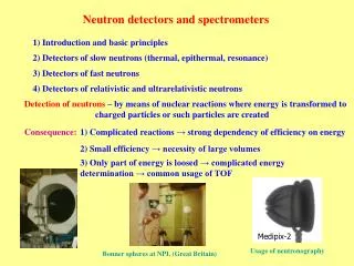
Xth International school of neutron scattering Francesco Paolo Ricci. Detectors for neutron scattering. M. Tardocchi tardocchi@ifp.cnr.it Istituto di Fisica del Plasma, EURATOM-ENEA-CNR Association, Milan, Italy. Nomenclature. What does it mean detecting a neutron ?

E N D
Xth International school of neutron scattering Francesco Paolo Ricci Detectors for neutron scattering M. Tardocchi tardocchi@ifp.cnr.it Istituto di Fisica del Plasma, EURATOM-ENEA-CNR Association, Milan, Italy
What does it mean detecting a neutron ? Need to produce some sort of measurable quantitative (countable) electrical signal It is not possible to detect directly slow neutrons (they carrry to little energy). It can be done with fast neutrons Neutrons are non ionizing particles. They interact via nuclear force. Nuclear reactions needed to convert neutrons in charged secondary particles(n,a), (n,p), (n, fission),(n,g) Cross sections S=N·s ; Stot = Sscatt + Srad capt + … ; neutron flux F (n·s-1·cm-2) Typical charged particle detectors can be used: Gaseous proportional counters & ionization chambers Scintillation detectors Semiconductors detectors (n,g) used in the Neutron Resonant Capture detector Neutron detection
Schematics of nuclear reactions 3 1 2 Energy conservation M1+M2 +T1= M3+M4 +T3+T4 (1) 4 • 1 Elastic collision (rest) mass and Tkin are conserved; M1=M2 ; M3=M4 • 2 Anelastic collision* mass is conserved, Tkin is conserved • 3 Nuclear reactions mass and Tkin are not conserved • Q= ( M1+M2) – (M3+M4) (2) Q-value defintion • Condensed matter scientist use the term anelastic to mean reaction • of type 1 when En initial≠ En final (exchange of and )
Schematics of nuclear reactions 3 1 2 4 Energy conservation M1+M2 +T1= M3+M4 +T3+T4 (1) eq1 +2 (T3+ T4) – T1= Q M1= M3, M2= M4 and Q =0 Elastic reactions M1= M3, M2= M4 and Q≠0 Anelastic reactions Q<0 Endhotermic Mass is created from kin. energy Q>0 Esothermic Mass is trasnformed in kinetic energy M1≠ M3 or M2≠ M4 and Q≠0 Nuclear reactions
n + 3He 3H + 1H + 0.764 MeV n + 6Li 4He + 3H + 4.79 MeV n + 10B 7Li* + 4He7Li + 4He + 0.48 MeV +2.3 MeV (93%)7Li + 4He +2.8 MeV ( 7%) n + 155Gd Gd* -ray spectrum conversion electron spectrum n + 157Gd Gd* -ray spectrum conversion electron spectrum n + 235U fission fragments + ~160 MeV n + 239Pu fission fragments + ~160 MeV Some nuclear reactions for neutron detection
Detectors for slow neutrons Ideal dector: High detection efficiency (cross section) Large Q values Stop reaction products Immune to bakground (often g rays) Ekinetics of the products=Q + En=Q Products emitted back-to-back (Pinit~0) …
Reactions for slow neutron detection • n + 10B (a.i20%)7Li* + a 7Li + a + 0.48 MeV + 2.3 MeV (93%) 3840 barns7Li + 4He + 2.8 MeV ( 7%) • n + 3He 3H + 1H + 0.764 MeV (expensive) 5330 barns • n + 6Li (a.i. 7%)4He + 3H + 4.79 MeV(resonance at 100keV)940 barns 10-2 105
Gas Detectors Ionization tracks in proportional counter gas Electrons drift toward the central anode wire. When they get close, they accelerate sufficiently between collisions with gas atoms to ionize the next atom. A Townsend avalanche occurs in which the number of electrons (and ions) increases the number many-fold, about x103. Separation of these charges puts a charge on the detector, which is a low-capacitance capacitor, causing a pulse in the voltage that can be amplified and registered electronically. 9
Ionization Mode Electrons drift to anode, producing a charge pulse with no gas multiplication. Typically employed in low-efficiency beam-monitor detectors. Proportional Mode:electron collisions ionize gas atoms producing even more electrons. Gas amplification increases the collected charge proportional to the initial charge produced. Gas gains of up to a few thousand are possible, above which proportionalityis lost. Gas Detectors – operational modes 10
Gas Detectors Proportional counters (PCs) come in a variety of different forms. Simple detector Linear position-sensitive detector (LPSD): The anode is resistive, read out from both ends—the chargedistributes between the ends according to the position of the neutron capture event in the tube. Usually cylindrical. 2-D position-sensitive detector (MWPC). Many parallel resistive wires extend across a large thick area of fill gas. Each wire operates either as in LPSD or without position. information as in a simple PC. or Two mutually perpendicular arrays of anode wires. Each is read separately as an LPSD to give two coordinates for the neutron capture event. MWPCs usually have a planar configuration. 11
Gas proportional counter ~25,000 ions and electrons produced per neutron 12
BF3 detector response function For large BF3 detectors the secondaries are completely absorbe In small BF3wall effect is present Range in BF3a~1cm @1ATM
Pulse Height Discrimination Can set discriminator levels to reject undesired events (fast neutrons, gammas, electronic noise). Pulse-height discrimination can make a large improvement in background. Discrimination capabilities are an important criterion in the choice of detectors (3He gas detectors are very good). 14
Multi-Wire Proportional Counter Array of discrete detectors. • Remove walls to get multi-wire counter. 17
MWPC Segment the cathode to get x-y position 18
Efficiency of Detectors Full expression: eff= 1 - exp(-N· sigma · d). Detectors rarely register all the incident neutrons. The ratio of the number registered to the number incident is the efficiency. • Approximate expression for low efficiency: • eff= N·sigma ·d. • Here: sigma= absorption cross-section (function of wavelength) • N = number density of absorber • d = thickness • N = 2.7 x 1019 cm-3per atm for a gas at 300 K. For 1-cm thick 3He at 1 atm and 1.8-Å neutrons, = 0.13. For a real 3d detector geometry Monte Carlo codes are needed in order to calculated the detector efficiency, 20
Spatial Resolution of Proportional Counters Spatial resolution (how well the detector tells the location of an event) is always limited by the charged-particle range and by the range of neutrons in the fill gas, which depend on the pressure and composition of the fill gas. And by the geometry: Simple PCs: d z ~ diameter; 6 mm - 50 mm. LPSDs: d z ~ diameter, d y ~ diameter ; 6 mm - 50 mm. MWPC: d z and d y ~ wire spacing; 1 mm - 10 mm. 21
Fission Counters Ionization chamber coated in its inner surface with fissile deposit. One of the the two fission fragment can be detected. Very large Q value (180-200MeV) With large thickness of fissile material deposition (UO2) the fission fragments may lose a significant fraction of their energy in the material itself thus releasing less energy into the detector
Fission cross sections Pu239 U235 Thermal neutron region 0.001 Energy (ev) 1.0 U235 Pu239 Fast neutron region U238 Np237 104 Energy (ev) 108
Some Common Scintillators for Neutron Detectors Intrinsic scintillators contain small concentrations of ions (“wave shifters”) that shift the wavelength of the originally emitted light to the longer wavelength region easily sensed by photomultipliers. ZnS(Ag) is the brightest scintillator known, an intrinsic scintillator that is mixed heterogeneously with converter material, usually Li6F in the “Stedman” recipe, to form scintillating composites. These are only semitransparent. But it is somewhat slow, decaying with ~ 10 µsec halftime. GS-20 (glass,Ce3+) is mixed with a high concentration of Li2O in the melt to form a material transparent to light. Li6Gd(BO3)3 (Ce3+) (including 158Gd and 160Gd, 6Li ,and 11B), and 6LiF(Eu) are intrinsic scintillators that contain high proportions of converter material and are typically transparent. An efficient gamma ray detector with little sensitivity to neutrons, used in conjunction with neutron capture gamma-ray converters, is YAP (yttrium aluminum perovskite, YAl2O3(Ce3+)). 26
Some Common Scintillators for Neutron Detectors Material Density of 6Li atoms (cm-3) Scintillation efficiency Photon wavelength (nm) Photons per neutron 0.45 % Li glass (Ce) 1.75x10²² 395 nm ~7,000 2.8 % 470 ~51,000 LiI (Eu) 1.83x10²² 9.2 % ZnS (Ag) - LiF 1.18x10²² 450 ~160,000 Li6Gd(BO3)3 (Ce), ~40,000 3.3x10²² ~ 400 -- YAP 350 ~18,000 per MeV gamma 27
Hamamatsu Multicathode Photomultiplier Compact photomultipliers are essential components of scintillation area detectors. The figure shows a recently developed multicathode photomultiplier, Hamamatsu model 8500. 29
Principle of Crossed-Fiber Position-Sensitive Scintillation Detector Outputs to multi-anode photomultiplier tube 1-mm-square wavelength- -shifting fibers Outputs to coincidence-encoded single-anode photomultiplier tubes Scintillator screen 30
16-element WAND Prototype Schematic and Results Clear Fiber 2-D tube Coincidence tube Neutron Beam Wavelength-shifting fiber Aluminum wire Scintillator Screen 31
Crossed-Fiber Scintillation Detector Design Parameters (ORNL I&C) Size: 25-cm x 25-cm. Thickness: 2-mm. Number of fibers: 48 for each axis. Multi-anode photomultiplier tube: Phillips XP1704. Coincidence tube: Hamamastu 1924. Resolution: < 5 mm. Shaping time: 300 nsec. Counting-rate capability: ~ 1 MHz. Time-of-flight resolution: 1 msec. 32
SNS 2-D Scintillation Detector Module Shows scintillator plate with all fibers installed and connected to multi-anode photomultiplier mount. 33
Normalized scattering from 1-cm-high germanium crystal. En ~ 0.056 eV. Detector 50 cm from crystal. Neutron Scattering from Germanium Crystal Using Crossed-Fiber Detector 34
Neutron Detector Screen Design The scintillator screen for this 2-D detector consists of a mixture of 6LiF and silver-activated ZnS powder in an optical grade epoxy binder. Neutrons incident on the screen react with the 6Li to produce a triton and an alpha particle. These charged particles passing through the ZnS(Ag) cause it to emit light at a wavelength of approximately 450 nm. The 450-nm photons are absorbed in the wavelength-shifting fibers where they convert to 520-nm photons, some of which travel toward the ends of the fibers guided by critical internal reflection. The optimum mass ratio of 6LiF:ZnS(Ag) is about 1:3. The screen is made by mixing the powders with uncured epoxy and pouring the mix into a mold. The powder settles to the bottom of the mold before the binder cures. The clear epoxy above the settled powder mix is machined away. The mixture of 40 mg/cm2 of 6LiF and 120 mg/cm2 of ZnS(Ag) used in this screen provides a measured neutron conversion efficiency of over 90% for 1.8 Å neutrons. 35
Spatial Resolution of Area Scintillation Detectors The spatial resolution accomplishable in SDs is typically better than in gas detectors. The range of neutrons is less. The range of ionizing particles is less in solid materials than in gases. However, the localization of the light source (an optical process) imposes the limit on position resolution. This in turn depends statistically on the number of photons produced in the scintillator (more is better, of course). 2000-03449/arb 36
Coating with Neutron Absorber-Surface-Barrier Detectors Layer (6Li or 10B) must be thin (a few microns) for charged particles to reach the detector. Detection efficiency is low. Most of the deposited energy doesn’t reach detector. Poor pulse-height discrimination 38
Semiconductor Detectors ~1.5 106 holes and electrons produced per neutron (large number comapre to scintilator and gas detectors) The detector acts as a capacitor. The ionization partially discharges the capacitor and can be detected directly without further amplification. However, standard device semiconductors do not contain enough neutron-absorbing nuclei to give reasonable neutron detection efficiency. Options: i) Put neutron absorber on surface of semiconductor? These exist and are called surface barrier detectors. ii) Develop, for example, boron phosphide semiconductor devices? This is a challenge for future development. 39
Epithermal neutrons from spallation sources • For moderatoirs at ISIS • H2O @ 300 K (two types) • H2 liquid @ 20 K • CH4 liquid @ 100 K
The Time of flight technique V Proton detector Spllation target LLD Flight path p tempo t 1= L/V1 t 2= L/V2 TF = 20 ms 1 start and e multi-stop fro mthe detector in one frame of 20 ms Dt = 3-5 ms
L0 E0, v0 q E1, v1 L1 Time of flight neutron spectroscopy in inverted geometry sample moderator resonant foil
Total Cross Section of Tantalum Tantalum is essentially monoisotopic 181Ta and is used as a neutron converter sensitive to energies near 4.28 eV. 1 101 102 103 104 Energy (meV) 43
n Neutron Detector (Lithium glass scintillator) n’ n’ n Gamma Detector (YAP scintillator) X n’ g Neutron detection techniques for epithermal neutrons FD (filter detector) RD (resonance detector)
TOF spectra for FD (neutron detector) and RD (g detector) RDT Pb sample U foil FDT
Resonance Detector principles • Two step process • i) Neutron absorption and conversion trough (n,g)reaction • ii) Detection of the emittedprompt gammas • RD properties • -The absorbing resonance fixes the final neutron energy • -Neutron conversion controls mainly the energy resolution (DE/E) • -Ability to detect gammas controls the signal to background ratio (S/B) • Advantages over Li-glass detectors • no principle need for background subtraction • no 1/v decrease of the detection efficiency: • i) detection efficiency not dependent on the neutron energy • ii) high efficiency for epithermal neutrons (10-100 eV)
Choice of the resonant element • Neutron absorbing resonance • E0 neutron resonance energy • s0 peak cross section (at E=E0) • G (FWHM) intrinsic resonance width • Criteria for resonant elements • Resonance energy: E0=10-100 eV • Isolated resonance (to avoid overlapping with other resonances) High cross section (high conversion efficiency) s0 = 104-105 b
Narrow resonance (low DE/E) • G~ 100 meV • D~ 100 meV (Thermal Doppler broadening) • Foil thickness • Compromise between neutron absorption probability, P(En), andDE/E • Nds0=1 • High yield of low energy gammas (10-300 keV) choice of suitable detector • Other desiderable features: high isotopic abundance, exist as metallic or oxide, low gamma self-absorption
Best Isotopes • Gamma yield (absolute) exists for thermal neutron capture, but incomplete database for resonant neutron capture • 139La57 218 keV 9 % 238U92 12 keV 32 % • 288 keV 9 % 48 keV 13 % • 60 keV 12 % • 150Sm62 65 keV 30 % 134 keV 94 % 105 keV 9 % 4060 keV 7 % 168 keV 8 %