Download
1 / 10
100 likes | 257 Views
Update on Advanced LIGO suspension design and technology development towards the quad noise prototype. Caroline A. Cantley for Advanced LIGO Suspension Team / University of Glasgow /GEO600 Group LSC Meeting, LLO March 2005 LIGO-G050107-00-K. Advanced LIGO suspension team.

E N D
Update on Advanced LIGO suspension design and technology development towards the quad noise prototype Caroline A. Cantley for Advanced LIGO Suspension Team / University of Glasgow /GEO600 Group LSC Meeting, LLO March 2005 LIGO-G050107-00-K
Advanced LIGO suspension team • LIGO Lab : CIT: H. Armandula, M. Barton, D. Coyne, J. Heefner, M. Mageswaran, K. Mailand, J. Romie, C. Torrie. MIT: P. Fritschel, K. Mason, R. Mittleman, L. Ruet, D. Shoemaker LHO: B. Bland, D. Cook LLO: J. Hanson, H. Overmier, O. Spjeld, G. Traylor • GEO600: Glasgow: G. Cagnoli, C. Cantley, A. Cumming, D. Crooks, E. Elliffe, A. Grant, A. Heptonstall, J. Hough, R. Jones, I. Martin, M. Perreur-Lloyd, M. Plissi, D. Robertson, S. Rowan, K. Strain, P. Sneddon, H. Ward Universitat Hannover: H. Lueck • Stanford University: N. Robertson (also GEO/Glasgow) • Rutherford Appleton Laboratory (CCLRC): J. Greenhalgh, T. Hayler, I. Wilmut • University of Birmingham: S. Aston, D. Hoyland, C. Speake, A. Vecchio, M. Cruise • Strathclyde University: N. Lockerbie
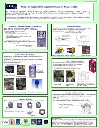
Quad controls prototype • US in collaboration with UK • First quad suspension build Caltech May ’05 • check/refine assembly & disassembly procedure • interference check • matching of blade stiffness & deflection – blade test facility (RAL) • handling of blades – blade flattener • Structural resonance testing • modal frequency measurement (Caltech) • coupled dynamics (ETF Stanford) Jun ‘05 • Due to be installed LASTI Jul’05 all metalprototype Dynamic structural analysis 1st mode 90 Hztarget 100 Hz + 15% Controls prototype ETM quad suspension and structure Talks by J. Romie (next) + C. Torrie (Tues p.m.) (CIT, Glasgow, Stanford, RAL, B’ham)
Hybrid OSEM design OSEM development • Birmingham/Strathclyde with input from Glasgow, RAL & LIGO • Modified Hybrid OSEMs meet performance requirements • Good low frequency performance expected ~ 1 x 10⁻¹⁰ m/Hz at 1Hz ~ 0.6 mm (p-p) working range • Production optimisation of Hybrid OSEM electromechanical design • Fabrication of a small quantity of prototype devices underway • Electronics & OSEM testing begins April at Birmingham • Schedule permitting, may test in quad controls prototype Talk by S. Aston (Tues p.m.) (Aston, Cantley, Greenhalgh, Hoyland, Lockerbie, Robertson, Speake, Strain, Vecchio, Ward)
Quad noise prototype • Final stage is monolithic (based on GEO600 technology) • Silica test & penultimate mass • Silica ribbons • Silica attachment ears • Assembly • Mass catcher/assembly jig design + handling of 40 kg silica masses • Effect of test mass material downselect to silica • Ear bond area • Ribbon taper shape – flexure positions / thermal noise • Manufacturing tolerance & alignment specifications • Monolithic suspension workshop held in Glasgow Jan 05 Mass catcher/assembly jig – formspart of lower structure monolithic finalstage Noise prototype (silica) ETM quad suspension and upper structure (lower structure not shown here) (Glasgow, RAL, CIT, Stanford, B’ham)
Optic ear development – design criteria • GEO 10 kg masses (bond area 2 x 3 cm2) • Design drivers • mechanical strength • silicate bond thermal noise • Ear geometry/position • ribbon flexure point offsets • minimise peeling effect • Ideally would scale bond area to keepstress levels as per GEO • 40 kg mass would require total bond area 24 cm2 • But bond thermal noise is a limitation • FE analysis of inhomogeneous thermal noise associated with silicate bonds FE model for prediction of inhomogeneous thermal noise associated with silicate bonds. Bond image: bonds are 81 nm thick. (Cagnoli, Cantley, Crooks, Elliffe, Heptonstall, Hough, Jones, P-Lloyd, Rowan)
Limit on ear bond area due to thermal noise Systems Design Requirement:Any technical noise source equivalent strain noise must be less than 10% of the target strain sensitivity Baseline displacement noise (per test mass) at 100 Hz is 8 x 10-21 m/Hz Yields total allowable bond area of 7.1 cm2 (~ x 6 safety margin based on previous bond strength tests) Adv LIGO:4 ears each of 1.7 cm2 Strain sensitivity with 40 kg fused silica test massand beam radius 5.5cm
Optic ear design & test • Designed to reduce peeling effect and increase strength • Separate ears for each ribbon (4 off total) • Disadvantage: more bonding effort • Strength testing: load using nailended wire • Rigorous failure tests will be conducted (Glasgow/CIT) • Test ears fabricated end May 05 Ribbon weldposition Load Silica test mass showing bonded silica attachment ears for welding the ribbons in the monolithic final stage. Inverted ears used on penultimate mass. (Armandula, Cagnoli, Cantley, Crooks, Elliffe, Heptonstall, Hough, Jones, P-Lloyd, Rowan)
CO2 laser pulling & welding of fibres • Fibres pulled up to 570 mm long • avg diameter 184 mm with standard deviation 5 mm • Ribbon pulling commenced • move to to variable feed-pull to achieve 10:1 aspect ratio • Welding demonstrated - strength tests start soon on ribbons and welds • effect of annealing on weld strength will be investigated • Q measurements on laser pulled ribbons is in initial stages • Intensive development & characterisation period over next six months PULL Silica fibre FEED Silica rod CO2 laser beam 10.6mm Fixed45° mirror 250 mm fibre being pulled using feed & pull technique with CO2 laser Conical mirror Rotating45° mirror Motor Talk by C. Cantley (Tues p.m.) concept schematic (Cagnoli, Cantley, Crooks, Martin, Cumming, Jones, Heptonstall, Rowan, Hough)
Future work • Continue to prepare for Controls Prototype installation in LASTI (July ’05) • Continue to develop noise prototype – monolithic final stage design • Test ears will be manufactured - testing will commence at Glasgow/Caltech (June ’05) • Continue to develop CO2 laser pulling & welding machine – next phase variable feed & pull for ribbons • Ribbon characterisation – strength testing & weld strength/annealing + long term suspension of 40 kg masses • Noise prototype installation in LASTI (Aug ’06)