Download
1 / 14
140 likes | 148 Views
Advanced LIGO. Detector upgrade is planned for 2011-2014 Factor of 10 increase in distance probed (‘reach’) Factor of 1000 increase in event rate Fabrication began in 2009 Long lead time parts Mirror blanks, polishing, coating. The LIGO Detector. Advanced LIGO. 125 W laser

E N D
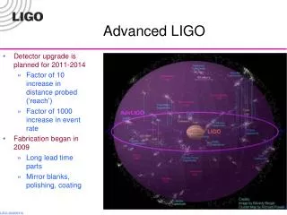
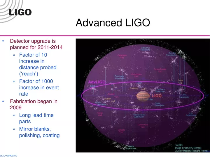
Advanced LIGO • Detector upgrade is planned for 2011-2014 • Factor of 10 increase in distance probed (‘reach’) • Factor of 1000 increase in event rate • Fabrication began in 2009 • Long lead time parts • Mirror blanks, polishing, coating
The LIGO Detector Advanced LIGO • 125 W laser • Quadruple pendulum • suspensions • Improved seismic isolation • Signal recycling • Stable recycling cavities • DC readout
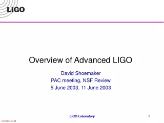
180 W laser Advanced LIGO Mirror Suspensions Seismic isolation Mirrors
Advanced LIGO • Advancements Initial LIGO Sensitivity
Schedule (approximate) (at LLO) • S6 (Science run 6) will end in Oct 2010 • Initial LIGO parts to be removed from chambers Nov 2010 • Install hutch/cleanroom for laser, move HAM 1 for in-vacuum signals detection, new larger tube to connect HAM 2/3, clean chambers and lab. Nov 2010–Jan 2011 • Install new seismic isolation Jan–Feb 2012 (staggered) • Install PSL and IO components Feb–July 2011 • Install vertex core optics, quad suspensions Oct 2011–Mar 2012 • Test PSL/IO/Power recycled short Michelson Mar 2012 • Install seismic isolation and quad suspensions Oct 2011–July 2012 • Commissioning July 2012–June 2013 • LHO (H1+H2) in 2014
The input optics (IO) PSL = pre-stabilized laser COC = core optical components IMC = input mode cleaner ISC = interferometer sensing and control PRM = power recycling mirror SRM = signal recycling mirror The input optics (IO) conditions the PSL laser light and delivers it to the interferometer. It provides: RF modulation for length and alignment control functions Power control Laser mode cleaning and frequency stabilization Isolation of laser from interferometer reflected light Optical signal distribution to length and alignment control Mode matching to recycling and arm cavities Design and fabrication of small PRMs and SRMs 6 6
Electro-optic modulator • Modulators use rubidium titanyl phosphate (RTP) • Electro-optic response similar to LiNbO3 • low absorption low thermal lensing • Multiple electrode configuration • Wedge, to reduce RFAM from polarization impurity • RF matching circuit in separate housing • Installed in enhanced LIGO at both sites
EOM performance Modulator tested to 140 W 300 hours sustained exposure of 100 W; >1 year at 30 W Modulation indices up to 0.8 8
Input Mode Cleaner • Triangular ring cavity • Length, L/2 = 16.5 m • FSR = 9.1 MHz • Finesse = 520 • Pstore = 23,200 W (@ 165 W input) • All three mirrors on SUS-supplied “mode-cleaner triple suspensions” • Occupies HAM2 and HAM3 in straight interferometers (L1, H1) • HAM8 and HAM9 in folded interferometer (H2) FSR = free spectral range SUS = suspensions subsystem HAM = horizontal access module chamber 9
Faraday Isolator Faraday Rotator Design TGG Holders • IAP/UF design and construction • Passively compensated (for depolarization and thermal lensing) • Consists of 2x calcite polarizers, 2x TGG crystals, quartz rotator, l/2 plate and –dn/dT DKDP thermal compensator • Observed >50 dB isolation (in lab) Bo Bo IAP = Institute of Applied Physics, Nizhny Novgorod TGG = terbium-gallium garnet DKDP = deuterated potassium dihydrogen phosphate, KD2PO4 10
Faraday for enhanced LIGO Faraday installed in enhanced LIGO, both sites FI giving 25 dB isolation, 1-18 W; 20 mrad REFL drift (L1 data)
Other items • Power control: motorized waveplate and 2x thin-film polarizers on PSL table, behind EOMs. T ~ 98%. Extinction ratio 140,000:1 • Mode-matching to IMC: 2 lens telescope on PSL table • Periscope: Oil derrick • Injection into vacuum: viewport on HAM1, sealed beam pipe to HAM2 • Errant beam baffles: silicon carbide for places where high-intensity beams could go PSL = pre-stabilized laser; EOM = electro-optic modulator IMC = input mode cleaner HAM = vacuum chamber 12
Other items 2 • Mode-matching to PRC: PMMT mirrors on SOS • IO carries PRC and SRC layout, radii for mode-matching to arms • Active control of mode matching with 4-heater thermal lens on SF57 glass plate • Diagnostics: RFAM monitor, cameras, optical spectrum analyzer PRC = power recycling cavity PMMT = pre-mode-matching telescope SOS = small optic suspension IO = input optics SRC = signal recycling cvity 13
Project Status: parts fabrication IMC mirror Substrate in transport container SM mirror substrates IMC mirror substrates Laser engraving RTP crystals 14