Download
1 / 12
120 likes | 230 Views
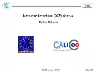
Status of the DHCAL DIF Detector InterFace Board. Sébastien Cap, Guillaume Vouters, Julie Prast. Aims of the DHCAL DIF. Interface DHCAL ASUs with the DAQ Configure the VFE chips Perform digital readout Power cycling, … LDA interface (final DAQ)

E N D
Status of the DHCAL DIFDetector InterFace Board Sébastien Cap, Guillaume Vouters, Julie Prast
Aims of the DHCAL DIF • Interface DHCAL ASUs with the DAQ • Configure the VFE chips • Perform digital readout • Power cycling, … • LDA interface (final DAQ) • PC interface through USB for debug and standalone. • Others : • Micromegas and RPC • Asics : Hardrocs or Lyon’s chip The DHCAL DIF Board
Architecture of the DIF Board DIF Power Supplies+ 6V +5V 3.3V 2.5V 1.2V LDO Mezzanine Monitoring 90 89 JTAG FPGA EP3C6F484 ASIC Config ASIC read DAQ interface Slow control SLAB USB LDA (HDMI) HR analog 2 1 ADC DIF The DHCAL DIF Board
SLAB Interface compliant with the DIF task force => The DHCAL DIF can also be used for ECAL or AHCAL … Samtec FSH/ SFMH 90 pin connector The DHCAL DIF Board
The DHCAL M2 Architecture 32 cm *48 cm ASU 24 HardRocs DIF Intermediate board DIF DIF FH31H flat Hirose connector (micromegas) or soldering (RPC) The DHCAL DIF Board
Design of a 1m2 MicroMegas Top (2mm SS)+ Drift Cathode Fibreglass 1002 6 Bulks (6MESH + 6ASU + 144 FE chips) with 5 mm gap 3 DIF Bottom (2mm SS) Joint I. Monteiro The DHCAL DIF Board 15 April 2008 SiD Collaboration Meeting 6
Status of the DHCAL prototype • Sent to production on April 29 th. • 10 PCB are manufactured. • Cabling in progress. • Boards awaited next week. The DHCAL DIF Board
Mechanical and Electrical Characteristics • 8 cm *10 cm *1.5 mm • 10 layers • 4 signal layers • Controlled impedance • Classe 6 (0.12 mm wire) DIF Top View Many thanks to Sébastien Cap for the CAD. The DHCAL DIF Board
Firmware Status • USB interface OK • R/W registers, commands, … • Slow control OK • HardRoc configuration • Return signal (SC_q) check • Acquisition and Digital Readout : to be tested (TBT) • Analog readout: TBT • Monitoring TBT • LDA interface : to be dvlped DAC output (V)= f (SC DAC value) • Software is developed by Christophe Combaret (IPN Lyon). See his talk • Congratulations to Guillaume Vouters for the main VHDL part. The DHCAL DIF Board
FW validation on the HR test board • LAL HardRoc test board • 1 HR + Cyclone FPGA. • 12 bits ADC for the analog RO. • Possibility of charge injection. • USB interface. • FW debug with signal tap The DHCAL DIF Board
Validation of the DHCAL DIF • No ASU available with HR before …. ? • Emulation of HardRocs using an Altera evaluation kit. • Fit the HR VHDL (digital part) in the FPGA. • User defined IO connector to interface with the DIF. => Will allow validation of the DIF and FW for N HR User defined connector FPGA to emulate HardRocs The DHCAL DIF Board
Conclusion • DHCAL DIF will be back from production next week. • Firmware and corresponding software (Lyon) are in progress. • Debug on the HardRoc test board (1 HR). • Before ASU reception, the DIF will be tested using an Altera evaluation kit to emulate HardRocs. => Necessity to have a validated and reliable DIF for the November test beam. The DHCAL DIF Board