Download
1 / 15
150 likes | 244 Views
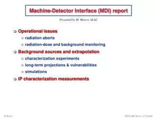
Detector Interface (DIF) Status. Mathias Reinecke. CALICE meeting – DESY. Dec. 2007. DIF environment – DAQ scheme. ODR: Off-Detector Receiver LDA: Link/Data Aggregator DIF: Detector (specific) Interface CCC: Clock/Control/Config. Aggregator (mostly common for all detectors).

E N D
Detector Interface (DIF) Status Mathias Reinecke CALICE meeting – DESY Dec. 2007
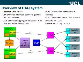
DIF environment – DAQ scheme ODR: Off-Detector Receiver LDA: Link/Data Aggregator DIF: Detector (specific) Interface CCC: Clock/Control/Config Aggregator (mostly common for all detectors) VFE Interface Electronics (common + detector specific parts) ECAL, DHCAL or AHCAL (VFE ASICs and detectors) From M. Wing et al. Mathias Reinecke CALICE meeting – DESY Dec. 2007
LDA Data Flow Data Flow includes: - Control and Configuration Path - Event Readout Path - Fast Access (timing related) From M. Kelly et al. Mathias Reinecke CALICE meeting – DESY Dec. 2007
LDA Prototype Design Commercial Spartan3 FPGA Board • Add-on boards for: • ODR-LDA interface (Ethn) • LDA-DIF interface (HDMI) • First prototypes expected • soon (Manchester). From M. Kelly et al. Mathias Reinecke CALICE meeting – DESY Dec. 2007
LDA - DIF protocol ideas DIF Upstream example: -enables fast (8-bit) commands -block transfer for large amounts of data (e.g. configuration data) -acknowledge to LDA (link robustness) From B. Hommels and M. Goodrick et al. Mathias Reinecke CALICE meeting – DESY Dec. 2007
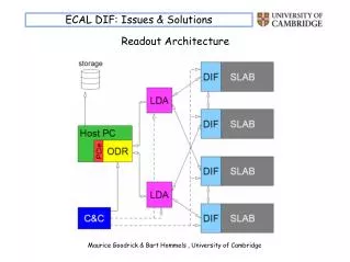
DIF common blocks From B. Hommels and M. Goodrick et al. Mathias Reinecke CALICE meeting – DESY Dec. 2007
DIF working group A „DIF Task Force“ has been established in order to exploit the synergies of the detector- and DAQ designs. • Bart Hommels (Cambridge) for the DAQ - Remy Cornat (Clermont) for the ECAL - Julie Prast (Annecy) for the DHCAL • - Mathias Reinecke (DESY) for the AHCAL • Signal interface DIF – Slab has been defined (ASIC prototypes). • VHDL programming in progress (DIF, test prototypes) • -Website with common VHDL blocks in preparation (J. Prast et al.) • -Current status and upcoming questions => report Mathias Reinecke CALICE meeting – DESY Dec. 2007
DIF – Slab Common Signal List List for ASIC‘s prototypes operation. Additional functionalities (e.g. failsafe) for next version under investigation. Mathias Reinecke CALICE meeting – DESY Dec. 2007
Power Cycling (e.g. SPIROCs) • Sequential power cycling of digital part during readout, • controlled by readout token. • (in this example: SPIROC with 5 analogue stages : • individual channel trigger, • SIPM noise above threshold rate ≈ 300Hz). Mathias Reinecke CALICE meeting – DESY Dec. 2007
DIF – AHCAL specific part Mathias Reinecke CALICE meeting – DESY Dec. 2007
AHCAL Half Sector - Reminder AHCAL Slab 6 HBUs in a row HBU HCAL Base Unit typ. 12 x 12 tiles SPIROC typ. 4 on a HBU HEB HCAL Endcap Board Hosts mezzanine modules: DIF, CALIBand POWER HLD HCAL Layer Distributor Mathias Reinecke CALICE meeting – DESY Dec. 2007
AHCAL: Unit CALIB • Gain calibration, -monitoring and operational tests by controlling the: POWERCALIBDIF • -Charge injection circuits • (SPIROC‘s charge inj. inputs) • Light calibration (LED) system • External trigger (without or in • combination with LCS) • Power cycling for electronics inside • detector layer To LDA Unit CALIB is fully controlled by the DIF (slave operation). Mathias Reinecke CALICE meeting – DESY Dec. 2007
AHCAL: Unit POWER+Monitoring • Power supply for the HBUs, • monitoring of temperature and • supply voltages POWERCALIBDIF • -Provide +3.5V, +5V and SiPM bias • voltages (+GND) to the HBUs • Read temperature monitors from • HBUs (inside gap) • Read voltage/current monitors of • supply voltages (outside gap). • Power cycling for electronics inside • detector layer To LDA Unit POWER is fully controlled by the DIF (slave operation). Mathias Reinecke CALICE meeting – DESY Dec. 2007
DIF: AHCAL specific part Very first idea about a possible setup. Mathias Reinecke CALICE meeting – DESY Dec. 2007
DIF – AHCAL Interconnection HBU Interconnection „Flexlead“ (4 layers in 300µm) POWERCALIBDIF Connector stacking height (both parts): 800µm Mathias Reinecke CALICE meeting – DESY Dec. 2007