Download
1 / 2
20 likes | 118 Views
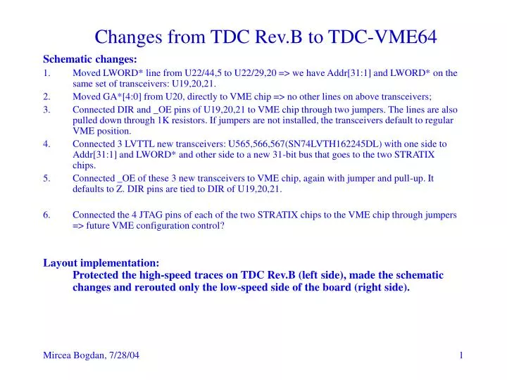
Changes from TDC Rev.B to TDC-VME64. Schematic changes: Moved LWORD* line from U22/44,5 to U22/29,20 => we have Addr[31:1] and LWORD* on the same set of transceivers: U19,20,21. Moved GA*[4:0] from U20, directly to VME chip => no other lines on above transceivers;

E N D
Changes from TDC Rev.B to TDC-VME64 Schematic changes: • Moved LWORD* line from U22/44,5 to U22/29,20 => we have Addr[31:1] and LWORD* on the same set of transceivers: U19,20,21. • Moved GA*[4:0] from U20, directly to VME chip => no other lines on above transceivers; • Connected DIR and _OE pins of U19,20,21 to VME chip through two jumpers. The lines are also pulled down through 1K resistors. If jumpers are not installed, the transceivers default to regular VME position. • Connected 3 LVTTL new transceivers: U565,566,567(SN74LVTH162245DL) with one side to Addr[31:1] and LWORD* and other side to a new 31-bit bus that goes to the two STRATIX chips. • Connected _OE of these 3 new transceivers to VME chip, again with jumper and pull-up. It defaults to Z. DIR pins are tied to DIR of U19,20,21. • Connected the 4 JTAG pins of each of the two STRATIX chips to the VME chip through jumpers => future VME configuration control? Layout implementation: Protected the high-speed traces on TDC Rev.B (left side), made the schematic changes and rerouted only the low-speed side of the board (right side).
Changes from TDC Rev.B to TDC-VME64 • Conclusions: • If the 3 jumpers are not installed, the new board should work in VME-32 mode with almost the same firmware as TDC Rev.B, just one minor modification to the STRATIX chip firmware and no modification for the VME chip. • To make the board work in VME-64 mode, will have to make extensive firmware changes in both the VME chip and the TDC chips. • This new design is not simulated/tested.