Download
1 / 1
30 likes | 241 Views
Florence. Naples. Trieste. CNR, Florence. Siegen. KTH, Stockholm. Bari. Calorimeter. ADSP2187. RESET. TRIGG. RS 422. BUSY. LVDS. ALARM. DSP controller e checker PM & DM. RS 422. TX Mux 1 in - 14 out. OUT-Buffers. LVDS. TTL. CMD Buffer. MAIN controller e multiplexer. TTL.

E N D
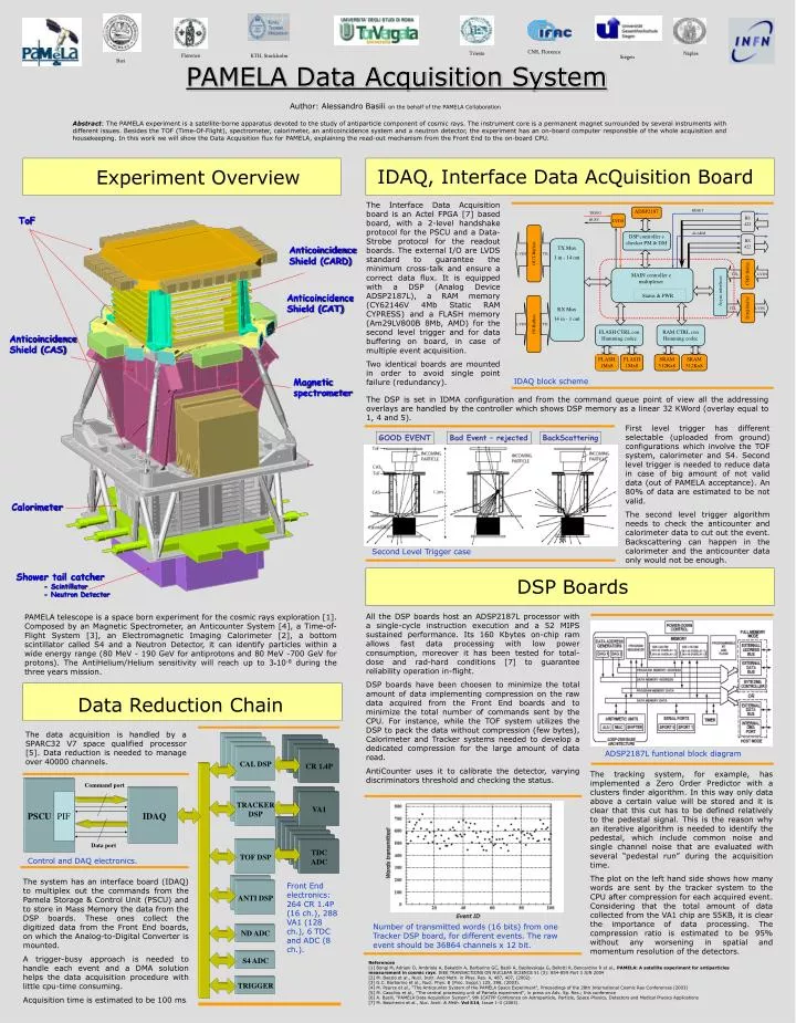
Florence Naples Trieste CNR, Florence Siegen KTH, Stockholm Bari Calorimeter ADSP2187 RESET TRIGG RS 422 BUSY LVDS ALARM DSP controller e checker PM & DM RS 422 TX Mux 1 in - 14 out OUT-Buffers LVDS TTL CMD Buffer MAIN controller e multiplexer TTL LVDS Async interfaces Status & PWR DAQ Buffer RX Mux 14 in - 1 out TTL LVDS IN-Buffers LVDS TTL FLASH CTRL con Hamming codec RAM CTRL con Hamming codec FLASH 1Mx8 FLASH 1Mx8 SRAM 512Kx8 SRAM 512Kx8 Words transmitted Event ID PAMELA Data Acquisition System Author: Alessandro Basili on the behalf of the PAMELA Collaboration Abstract: The PAMELA experiment is a satellite-borne apparatus devoted to the study of antiparticle component of cosmic rays. The instrument core is a permanent magnet surrounded by several instruments with different issues. Besides the TOF (Time-Of-Flight), spectrometer, calorimeter, an anticoincidence system and a neutron detector, the experiment has an on-board computer responsible of the whole acquisition and housekeeping. In this work we will show the Data Acquisition flux for PAMELA, explaining the read-out mechanism from the Front End to the on-board CPU. IDAQ, Interface Data AcQuisition Board Experiment Overview The Interface Data Acquisition board is an Actel FPGA [7] based board, with a 2-level handshake protocol for the PSCU and a Data-Strobe protocol for the readout boards. The external I/O are LVDS standard to guarantee the minimum cross-talk and ensure a correct data flux. It is equipped with a DSP (Analog Device ADSP2187L), a RAM memory (CY62146V 4Mb Static RAM CYPRESS) and a FLASH memory (Am29LV800B 8Mb, AMD) for the second level trigger and for data buffering on board, in case of multiple event acquisition. Two identical boards are mounted in order to avoid single point failure (redundancy). ToF Anticoincidence Shield (CARD) Anticoincidence Shield (CAT) Anticoincidence Shield (CAS) Magnetic spectrometer IDAQ block scheme The DSP is set in IDMA configuration and from the command queue point of view all the addressing overlays are handled by the controller which shows DSP memory as a linear 32 KWord (overlay equal to 1, 4 and 5). First level trigger has different selectable (uploaded from ground) configurations which involve the TOF system, calorimeter and S4. Second level trigger is needed to reduce data in case of big amount of not valid data (out of PAMELA acceptance). An 80% of data are estimated to be not valid. The second level trigger algorithm needs to check the anticounter and calorimeter data to cut out the event. Backscattering can happen in the calorimeter and the anticounter data only would not be enough. GOOD EVENT Bad Event – rejected BackScattering Second Level Trigger case Shower tail catcher - Scintillator - Neutron Detector DSP Boards All the DSP boards host an ADSP2187L processor with a single-cycle instruction execution and a 52 MIPS sustained performance. Its 160 Kbytes on-chip ram allows fast data processing with low power consumption, moreover it has been tested for total-dose and rad-hard conditions [7] to guarantee reliability operation in-flight. DSP boards have been choosen to minimize the total amount of data implementing compression on the raw data acquired from the Front End boards and to minimize the total number of commands sent by the CPU. For instance, while the TOF system utilizes the DSP to pack the data without compression (few bytes), Calorimeter and Tracker systems needed to develop a dedicated compression for the large amount of data read. AntiCounter uses it to calibrate the detector, varying discriminators threshold and checking the status. PAMELA telescope is a space born experiment for the cosmic rays exploration [1]. Composed by an Magnetic Spectrometer, an Anticounter System [4], a Time-of-Flight System [3], an Electromagnetic Imaging Calorimeter [2], a bottom scintillator called S4 and a Neutron Detector, it can identify particles within a wide energy range (80 MeV - 190 GeV for antiprotons and 80 MeV -700 GeV for protons). The AntiHelium/Helium sensitivity will reach up to 3•10-8 during the three years mission. Data Reduction Chain The data acquisition is handled by a SPARC32 V7 space qualified processor [5]. Data reduction is needed to manage over 40000 channels. VA1 VA1 VA1 ADSP2187L funtional block diagram CAL DSP CR 1.4P The tracking system, for example, has implemented a Zero Order Predictor with a clusters finder algorithm. In this way only data above a certain value will be stored and it is clear that this cut has to be defined relatively to the pedestal signal. This is the reason why an iterative algorithm is needed to identify the pedestal, which include common noise and single channel noise that are evaluated with several “pedestal run” during the acquisition time. The plot on the left hand side shows how many words are sent by the tracker system to the CPU after compression for each acquired event. Considering that the total amount of data collected from the VA1 chip are 55KB, it is clear the importance of data processing. The compression ratio is estimated to be 95% without any worsening in spatial and momentum resolution of the detectors. Command port VA1 TRACKER DSP VA1 PSCU PIF IDAQ TDC ADC TDC ADC TDC ADC TDC ADC TDC ADC Data port TOF DSP TDC ADC Control and DAQ electronics. The system has an interface board (IDAQ) to multiplex out the commands from the Pamela Storage & Control Unit (PSCU) and to store in Mass Memory the data from the DSP boards. These ones collect the digitized data from the Front End boards, on which the Analog-to-Digital Converter is mounted. A trigger-busy approach is needed to handle each event and a DMA solution helps the data acquisition procedure with little cpu-time consuming. Acquisition time is estimated to be 100 ms. Front End electronics: 264 CR 1.4P (16 ch.), 288 VA1 (128 ch.), 6 TDC and ADC (8 ch.). ANTI DSP Number of transmitted words (16 bits) from one Tracker DSP board, for different events. The raw event should be 36864 channels x 12 bit. ND ADC S4 ADC References [1] Bongi M, Adriani O, Ambriola A, Bakaldin A, Barbarino GC, Basili A, Bazilevskaja G, Bellotti R, Bencardino R et al., PAMELA: A satellite experiment for antiparticles measurement in cosmic rays. IEEE TRANSACTIONS ON NUCLEAR SCIENCE 51 (3): 854-859 Part 3 JUN 2004 [2] M. Boezio et al., Nucl. Instr. And Meth. in Phys. Res. A, 487, 407, (2002). [3] G.C. Barbarino et al., Nucl. Phys. B (Proc. Suppl.) 125, 298, (2003). [4] M. Pearce et al., “The Anticounter System of the PAMELA Space Experiment”, Proceedings of the 28th International Cosmic Ray Conferences (2003) [5] M. Casolino et al., ''The central processing unit of Pamela experiment'', in press on Adv. Sp. Res.; this conference [6] A. Basili, “PAMELA Data Acquisition System”, 9th ICATPP Conference on Astroparticle, Particle, Space Physics, Detectors and Medical Physics Applications [7] M. Boscherini et al., Nuc. Instr. & Meth.Vol 514, Issue 1-3 (2003). TRIGGER