Download
1 / 23
280 likes | 578 Views
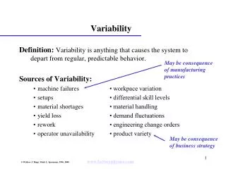
Process Variability. EE/MatE 167 David Wahlgren Parent. Introduction. Fabricator to Fabricator Variation: The differences in SPC data from fab house to fab house If you use the same fab house every time, you can optimize your design for one set of SPC data

E N D
Process Variability EE/MatE 167 David Wahlgren Parent EE/MAtE167
Introduction • Fabricator to Fabricator Variation: • The differences in SPC data from fab house to fab house • If you use the same fab house every time, you can optimize your design for one set of SPC data • If you need to be able to use any vendor, you must take care to not optimize for any one process EE/MAtE167
Intro Cont. • Inter-Die Variation: How much all your process parameters vary from chip to chip • This is the most commonly talked about form of variation. • Intra-Die Variation: How much your process parameters vary on the chip. EE/MAtE167
What Varies? • Everything but Planck’s constant and Boltzman’s constant • Threshold voltage • Gate oxide thickness • Doping in the channel • Channel Length • Fixed oxide charge • Threshold Voltage affects: • Current • Noise • Power • Speed of a circuit EE/MAtE167
Inter-Die Variations • Timing of circuits must take into account sources of delay variability • Functionality needs to be assured at the porcess extremes • Circuit designers love to blame the process when their designs have a low yield. • Rule of thumb • Designs need to allow for a +/- three sigma timing delay variation. EE/MAtE167
Sort percent yield dependence on process for a non-optimized design. • CLY Circuit Limited Yield • The number of parts that meet your performance spec (parts that fail totally are not included). • This design can not handle process variations. EE/MAtE167
Response variation can be caused by path compositional differences. • We are concerned with the ratio of various delays • Intrinsic delay: Unloaded CMOS stage delay. How much time is takes for the logic levels to stabilize before they are buffered up to drive large fan out or long wires. • RC delay: The delay associated with long wires or driving large fan outs. • Global critical paths: The slowest path for any signal. Any slow down on this signal will cause the circuit to fail the performance specification. • On a processor 95% intrinsic 5% RC to a 40/60 split. EE/MAtE167
Effect of varying path composition on functionality EE/MAtE167
Intra-Die Variation • Parameters that do not track on the die are of a particular concern. • Paths that are short are at risk, because these effects can not be averaged out over long paths. EE/MAtE167
Failure Causes • Race Conditions • If two signals are launched by the same event, then the timing relationship has to be preserved • If path A needs the results of path B then the circuit will fail if path A reads the data before path B has arrived. • Conventional timing • Standard timing margin, make sure everything is evaluated within a clock cycle. • Clock skew and jitter • Circuit fails EE/MAtE167
Failure Causes • Clock skew and jitter • Skew is when the clock arrives earlier or later from one logic gate to the other. • Jitter is when the period of the cclock varies over time. • Circuit fails • If a device property strays to far from design is can cause circuit logic styles to fail. EE/MAtE167
Front-End-Of-Line Variability Considerations EE/MatE 167 David Wahlgren Parent EE/MAtE167
Introduction • FEOL variability affects the response of discrete electrical components. • transistors, capacitors, resistors • MOSFET • Poly gate length • Spacer widths • Gate oxide thickness • Device width and edge effects EE/MAtE167
Threshold Voltage EE/MAtE167
Inter fab variation • Spacer thickness • Simple method • Large spacers • Leads to larger overlap variations • LDD • Narrow spacers • spacer then LDD implant • 20% spacer then S/D implant • Channel length can vary by 10% on die for even a mature process EE/MAtE167
Across the Chip Line-width Variation (ACLV) • How the line with varies on the die. • To combat ACLV have device gates: • have the same physical dimensions • oriented in the same direction • close together • have same nearest neighbor distances • are placed in area with similar pattern density. EE/MAtE167
NMOS to PMOS Length Tracking • The ratios of NMOS and PMOS driving capability vary. • Some styles are very dependant on this. • Even though the gates are etched at the same time, differences in spacers for pmos and nmos can affect LEFF • Some times they do not track • leff of nmos gets larger while pmos gets smaller across die. • Keep device length the same. • Keep everything close together. EE/MAtE167
Channel Width Variations • For narrow channel widths the threshold voltage can change. • Unlike SCE the effect can be directly proportional to width or inversely proportional with width fro fabrication house to fabrication house. EE/MAtE167
VT Variations • Everything varies but Planck’s constant and Boltzman’s constant • Threshold voltage • Gate oxide thickness • Doping in the channel • Channel Length • Fixed oxide charge • Mobile charge EE/MAtE167
Hot Carrier Effects • Degrades devices over the lifetime depending on how much they are used. • Since all gates are not used the same amount except for clock trees there will be a ID/VT variation that will creep in over time. • NMOS VT goes up ID goes down. • PMOS VT goes down ID goes up. EE/MAtE167
Type of HCE • Conducting • In “pinch off” Inversion region does not reach depletion region and carriers are inject with a high electric field. This gives them a high energy or temperature and it causes crystal damage. • Worse when VDD/2 • Slow slew rates or fast switching degrades FET even faster. • Energetic carriers get trapped in the gate oxide. EE/MAtE167
Drain Resistance Modulation • If spacer is too short dopant can get trapped in spacer thus lowering drain conductance. • If too large there is too much overlap capacitance and the speed goes down. EE/MAtE167
Other Variations • Negative Bias Temperature Instability • Inter fab variation • not well understood • aging • Body effect • Threshold voltage can vary if source is not tied to ground. EE/MAtE167