Download
1 / 101
1.01k likes | 1.02k Views
Chapter 11. Data Link Control. Stephen Kim (dskim@iupui.edu). FRAMING.

E N D
Chapter 11. Data Link Control Stephen Kim (dskim@iupui.edu)
FRAMING The data link layer needs to pack bits into frames, so that each frame is distinguishable from another. Our postal system practices a type of framing. The simple act of inserting a letter into an envelope separates one piece of information from another; the envelope serves as the delimiter.
Framing • To define boundaries of messages for distinguishing from other messages and signal. • Classification • Fixed-size framing: e.g.) ATM • Variable-size framing: e.g.) Ethernet • Character-oriented protocols • Bit-oriented protocols
Character-Oriented Protocols • To use special characters to indicate the beginning and the end of a frame • Good for exchanging text messages, but what if other type of information (graph, audio, video) that can carry any character pattern even same as the special character. • Byte-stuffing : Byte stuffing is the process of adding 1 extra byte whenever there is a flag or escape character in the text.
Bit-Oriented Protocols • Consider a frame as a sequence of bits. • Add special bit-pattern (e.g. 01111110) at the beginning and the end of a frame. • The data may contain THE special bit-pattern from the upper layer. • Bit stuffing is the process of adding one extra 0 whenever five(5) consecutive 1’s follow a 0 in the data, so that the receiver does not mistake the pattern 0111110 for a flag.
5 1 2 3 4 5 6 7 8 9 8 0 2 3 5 7 2 5 6 2 5 3 7 3 FR 1 FR 2 FR 3 FR 4 Other Framing - Character Count • Method • The header specifies the number of characters in the frame • D knows how many characters follow the header, or where the end of frame is. • What if a header is garbled? • D can not tell where the following frames are. • Retransmission does not work either. • No one uses this method for the network communication that is supposed to be unreliable.
Other Framing - Physical Encoding Violation • Applicable if the line encoding of physical medium contains some redundancy. • Send an invalid line encoding as a frame boundary. • Example • In Manchester encoding, valid line codes are 10 or 01. • Send 00110011 as a frame boundary.
FLOW AND ERROR CONTROL The most important responsibilities of the data link layer are flow control and error control. Collectively, these functions are known as data link control.
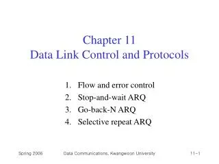
Data Link Control • Flow Control • Flow control refers to a set of procedures used to restrict the amount of data that the sender can send before waiting for acknowledgment. • Error control • Error control in the data link layer is based on automatic repeat request, which is the retransmission of data.
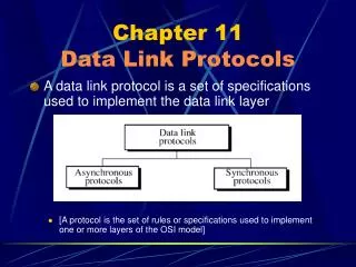
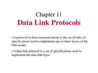
PROTOCOLS Now let us see how the data link layer can combine framing, flow control, and error control to achieve the delivery of data from one node to another. The protocols are normally implemented in software by using one of the common programming languages. To make our discussions language-free, we have written in pseudocode a version of each protocol that concentrates mostly on the procedure instead of delving into the details of language rules.
NOISELESS CHANNELS Let us first assume we have an ideal channel in which no frames are lost, duplicated, or corrupted. We introduce two protocols for this type of channel.
Simplest Protocol • No flow and error control.
Algorithm 11.1Sender-site algorithm for the simplest protocol Algorithm 11.2Receiver-site algorithm for the simplest protocol
Example 11.1 Figure 11.7 shows an example of communication using this protocol. It is very simple. The sender sends a sequence of frames without even thinking about the receiver. To send three frames, three events occur at the sender site and three events at the receiver site. Note that the data frames are shown by tilted boxes; the height of the box defines the transmission time difference between the first bit and the last bit in the frame.
time-out period S time FR-0 FR-1 FR-1 ACK ACK D Stop-and-Wait Protocol, 2 • In normal operation • S transmits a frame and wait for an ACK from D during a give time. • D transmits an ACK after receiving an error-free frame. • In case of a frame dropped • S retransmits the frame after the time-out period expires.
time-out period time-out period S FR-0 FR-1 FR-1 FR-1 ACK FR-1’ ACK ACK D time Stop-and-Wait Protocol, 3 • In case of frame garbled • D does nothing, and then S will retransmit. • In case of ACK dropped • S retransmits the frame • D receives the frame and transmits another ACK. • D will receive duplicated frames! • Add a sequence number to the frame • So, D will discard the second copy of the frame, but resend ACK.
Algorithm 11.3Sender-site algorithm for Stop-and-Wait Protocol Algorithm 11.4Receiver-site algorithm for Stop-and-Wait Protocol
Example 11.2 Figure 11.9 shows an example of communication using this protocol. It is still very simple. The sender sends one frame and waits for feedback from the receiver. When the ACK arrives, the sender sends the next frame. Note that sending two frames in the protocol involves the sender in four events and the receiver in two events.
NOISY CHANNELS Although the Stop-and-Wait Protocol gives us an idea of how to add flow control to its predecessor, noiseless channels are nonexistent. We discuss three protocols in this section that use error control.
Note • Error correction in Stop-and-Wait ARQ is done by keeping a copy of the sent frame and retransmitting of the frame when the timer expires. • In Stop-and-Wait ARQ, we use sequence numbers to number the frames. The sequence numbers are based on modulo-2 arithmetic. • In Stop-and-Wait ARQ, the acknowledgment number always announces in modulo-2 arithmetic the sequence number of the next frame expected.
time-out period FR-0 FR-0 FR-1 FR-2 S ACK delayed ACK D time Stop-and-Wait Protocol, 1 • In case of delayed ACK or prematured time-out. • S will retransmit the frame, say FR-0, after the time-out. • S receives an ACK, but what it is for? either for the first frame or for the retransmitted frame? • S sends the next frame, say FR-1 and receive an ACK. What is it for? FR-0 or FR-1? Add a sequence number to the ACK frame !!!
time-out period Slast 0 1 FR 0 FR 0 FR 1 ACK 0 ACK 0 ACK 1 Dnext 0 1 0 time-out period time-out period Slast 0 1 0 FR 0 FR 0 FR 1 FR 1 FR 2 ACK 0 delayed ACK 0 ACK 1 Dnext 0 1 0 time Size of Sequence Number • The number of frames to be sent is arbitrary, but the space for the sequence is finite (in header) • 1-bit sequence number is good enough for Stop-and-Wait. • Slast := # of frame in buffer of S (or to being sent). • Dnext := # of frame that D expects to receive
Algorithm 11.5Sender-site algorithm for Stop-and-Wait ARQ (continued)
(continued) Algorithm 11.5Sender-site algorithm for Stop-and-Wait ARQ
Algorithm 11.6Receiver-site algorithm for Stop-and-Wait ARQ Protocol
Example 11.3 Figure 11.11 shows an example of Stop-and-Wait ARQ. Frame 0 is sent and acknowledged. Frame 1 is lost and resent after the time-out. The resent frame 1 is acknowledged and the timer stops. Frame 0 is sent and acknowledged, but the acknowledgment is lost. The sender has no idea if the frame or the acknowledgment is lost, so after the time-out, it resends frame 0, which is acknowledged.
Performance of Stop-and-Wait Protocol • Assumption • Propagation delay : sec • Frame size: L bits • Bandwidth: r bit/sec • Ignore control frame size • Ignore processing delay and queuing delay • Performance • It sends an L-bits frame and wait at least 2+L/r sec • During this period, it is able to send (2+L/r)r=2r+L bits • Example • 20 msec propagation delay, 10 Mbps channel, frame size 1000-bit. • It make the channel busy for 100 usec out of 40.1 msec0.25% efficiency
Example 11.4 • Assume that, in a Stop-and-Wait ARQ system, the bandwidth of the line is 1 Mbps, and 1 bit takes 20 ms to make a round trip. What is the bandwidth-delay product? If the system data frames are 1000 bits in length, what is the utilization percentage of the link? • Solution • The bandwidth-delay product is(1*106)*(20*10-3)=20,000 bits • The system can send 20,000 bits during the time it takes for the data to go from the sender to the receiver and then back again. However, the system sends only 1000 bits. We can say that the link utilization is only 1000/20,000, or 5 percent. For this reason, for a link with a high bandwidth or long delay, the use of Stop-and-Wait ARQ wastes the capacity of the link.
Example 11.5 • What is the utilization percentage of the link in Example 11.4 if we have a protocol that can send up to 15 frames before stopping and worrying about the acknowledgments? • Solution • The bandwidth-delay product is still 20,000 bits. The system can send up to 15 frames or 15,000 bits during a round trip. This means the utilization is 15,000/20,000, or 75 percent. Of course, if there are damaged frames, the utilization percentage is much less because frames have to be resent.
time-out period 0 1 2 3 4 5 6 8 6 5 7 8 7 S 0 1 2 5 7 3 6 4 D Go-Back-N Protocol, 1 • Motivation • Inefficiency of Stop-and-Wait protocol • S continuously sends enough frames so that the channel is kept busy while S waits for ACK. • Procedure • S has a limit on the number of outstanding frames (Sw), and each frame is associated with a timer • S sends frame 0 followed by additional frames, so Sw frames are outstanding. • Upon receiving ACK k, S sends frames up to Sw + k. • If time-out occurs, go back to Sw previous frames (outstanding frames) which are outstanding in S, and re-transmit all those outstanding frames.
Go-Back-N Protocol, 2 • If errors occurs, the loss of transmission time for Sw frames. • In Stop-and-Wait, the loss was the time-out period. • Each outstanding frame is associated with a timer. • Outstanding frames are maintained by two variables: Sf and Sn. • Sf : the oldest outstanding frame. • Sn: the next frame to send. • Sn-Sf < Ssize. • D has a single state variable: Rn := the frame number to receive. • If D receives frame k for k = Rn, it sends an ACK for Rn and update Rn=Rn+1. • Upon receiving ACK(Rn), S update Sf = Rn and sends more frames such that at most Sw frames are outstanding. • Relations between the variables • Sf Rn<Sn and Sn-Sf < Sw
time-out period S time-out period D 0 2 1 3 0 2 1 S 1 2 3 1 2 0 1 0 1 This is the retransmission of fram 0 1 1 2 2 0 3 3 D 1 2 3 0 Is this fram 0 or frame 4? Go-Back-N Protocol, 3 • Size of Header (for sequence number) • m bits – capable of representing 0 to 2m - 1. • If Sw < 2m, S and D can say which frame has been received or acknowledged without ambiguity. • Example • Assume Sw=2m, for m=2 (4) • Assume Sw=2m-1, for m=2 (3)
N1 A3 A1 A2 9 6 0 2 3 5 1 4 8 2 7 3 4 5 6 7 1 S D 0 1 1 2 3 Go-Back-N Protocol, 4 • Improvement • D sends a NAK(Rnext) after the first out-of-sequence message • S retransmits from frames Rnext after receiving NAK(Rnext). • Piggybacking • In bi-directional communication, ACK or NAK is piggybacked to an information frame in reverse direction. • What if there no user data for a certain period of time? • ACK timer.
Summary, Goback-N Protocol • In the Go-Back-N Protocol, the sequence numbers are modulo 2m, where m is the size of the sequence number field in bits. • The send window is an abstract concept defining an imaginary box of size 2m − 1 with three variables: Sf, Sn, and Sw. • The send window can slide one or more slots when a valid acknowledgment arrives. • The receive window is an abstract concept defining an imaginary box of size 1 with one single variable Rn. The window slides when a correct frame has arrived; sliding occurs one slot at a time. • In Go-Back-N ARQ, the size of the send window must be less than 2m(not equal to !!!) the size of the receiver window is always 1.
Algorithm 11.7Go-Back-N sender algorithm (continued)
(continued) Algorithm 11.7Go-Back-N sender algorithm
Example 11.6 Figure 11.16 shows an example of Go-Back-N. This is an example of a case where the forward channel is reliable, but the reverse is not. No data frames are lost, but some ACKs are delayed and one is lost. The example also shows how cumulative acknowledgments can help if acknowledgments are delayed or lost. After initialization, there are seven sender events. Request events are triggered by data from the network layer; arrival events are triggered by acknowledgments from the physical layer. There is no time-out event here because all outstanding frames are acknowledged before the timer expires. Note that although ACK 2 is lost, ACK 3 serves as both ACK 2 and ACK 3.
Example 11.7 Figure 11.17 shows what happens when a frame is lost. Frames 0, 1, 2, and 3 are sent. However, frame 1 is lost. The receiver receives frames 2 and 3, but they are discarded because they are received out of order. The sender receives no acknowledgment about frames 1, 2, or 3. Its timer finally expires. The sender sends all outstanding frames (1, 2, and 3) because it does not know what is wrong. Note that the resending of frames 1, 2, and 3 is the response to one single event. When the sender is responding to this event, it cannot accept the triggering of other events. This means that when ACK 2 arrives, the sender is still busy with sending frame 3.