Download
1 / 107
1.09k likes | 1.41k Views
Chapter 11 데이터 링크 제어 (Data Link Control). 11 장 데이터 링크 제어와 프로토콜. 11.1 프레임 짜기 11.2 흐름 및 오류 제어 11.3 프로토콜 11.4 무잡음 채널 11.5 잡음 있는 채널 11.6 HDLC 11.7 점 대 점 프로토콜 11.8 요약. 11.1 프레임 짜기 (FRAMING).

E N D
Chapter 11 데이터 링크 제어 (Data Link Control)
11 장 데이터 링크 제어와 프로토콜 11.1 프레임짜기 11.2 흐름 및 오류 제어 11.3 프로토콜 11.4 무잡음 채널 11.5 잡음 있는 채널 11.6 HDLC 11.7 점 대 점 프로토콜 11.8 요약
11.1 프레임 짜기(FRAMING) The data link layer needs to pack bits into frames, so that each frame is distinguishable from another. Our postal system practices a type of framing. The simple act of inserting a letter into an envelope separates one piece of information from another; the envelope serves as the delimiter. Topics discussed in this section: Fixed-Size Framing Variable-Size Framing
프레임 짜기 1. 고정크기 프레임 2. 가변 크기 프레임 • 문자 중심 프로토콜 • 비트 중심 프로토콜
고정크기 프레임 • 고정 길이 또는 가변 길이 - 예 : ATM 광역네트워크의 셀(cell) • 가변크기 프레임 - 주로 LAN에서 사용 - 프레임이 끝나는 곳과 다음 프레임이 시작하는 곳 지정
문자 중심 프로토콜(A frame in a character-oriented protocol) • 전달되는 데이터는 코딩 시스템의 8비트 문자(부록 A) • 시작과 마지막에 플래그 추가 • 문자 중심 프로토콜 프레임
바이트 채워 넣기(stuffing) 와 빼기(unstuffing) • 정보 내에 플래그로 사용되는 패턴이 있을 경우 이를 플래그로오인하지 않게 하기 위한 것
Note 바이트 채우기는 텍스트에 플래그나 ESC 문제가 있을 때 여분의 1 바이트를 추가하는 처리이다. Byte stuffing is the process of adding 1 extra byte whenever there is a flag or escape character in the text.
비트 중심 프로토콜 • Bit-oriented protocol • 프레임의 데이터 부분을 전부 bit열로 인식 • 플래그는 “01111110”비트 패턴 사용 • 비트 중심 프로토콜의 프레임
Note 비트 채워 넣기는 수신자가 데이터 속에 있는 “01111110”을 플래그로 오해하지 않도록 “0” 다음에 연속되는 “1”이 다섯개 있으면 여분의 “0” 비트를 추가하는 처리이다. Bit stuffing is the process of adding one extra 0 whenever five consecutive 1s follow a 0 in the data, so that the receiver does not mistake the pattern 0111110 for a flag.
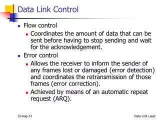
11.2 FLOW AND ERROR CONTROL The most important responsibilities of the data link layer are flow control and error control. Collectively, these functions are known as data link control. Topics discussed in this section: Flow ControlError Control
Note 흐름 제어는 송신자가 확인응답을 받기 전에 보낼 수 있는 데이터의 양을 제한하기 위해 사용하는 일련의 절차이다. Flow control refers to a set of procedures used to restrict the amount of data that the sender can send before waiting for acknowledgment.
Note 데이터링크 층의 오류제어는 데이터 재전송을 요구하는 ARQ를 기반으로 한다. Error control in the data link layer is based on automatic repeat request, which is the retransmission of data.
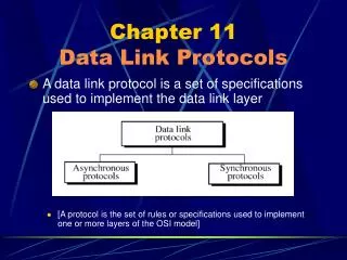
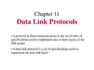
11.3 PROTOCOLS Now let us see how the data link layer can combine framing, flow control, and error control to achieve the delivery of data from one node to another. The protocols are normally implemented in software by using one of the common programming languages. To make our discussions language-free, we have written in pseudocode a version of each protocol that concentrates mostly on the procedure instead of delving into the details of language rules.
11.4 무잡음(NOISELESS) CHANNELS Let us first assume we have an ideal channel in which no frames are lost, duplicated, or corrupted. We introduce two protocols for this type of channel. Topics discussed in this section: Simplest Protocol Stop-and-Wait Protocol
흐름이나 오류제어 없는 가장 간단한 프로토콜 설계
Example 11.1 Figure 11.7 shows an example of communication using this protocol. It is very simple. The sender sends a sequence of frames without even thinking about the receiver. To send three frames, three events occur at the sender site and three events at the receiver site. Note that the data frames are shown by tilted boxes; the height of the box defines the transmission time difference between the first bit and the last bit in the frame.
정지-후-대기 프로토콜을 위한 송신측 알고리즘 (Sender-site algorithm for Stop-and-Wait Protocol)
정지-후-대기를 위한 수신측 알고리즘 (Receiver-site algorithm for Stop-and-Wait Protocol)
Example 11.2 Figure 11.9 shows an example of communication using this protocol. It is still very simple. The sender sends one frame and waits for feedback from the receiver. When the ACK arrives, the sender sends the next frame. Note that sending two frames in the protocol involves the sender in four events and the receiver in two events.
11.5 잡음 있는(NOISY) CHANNELS Although the Stop-and-Wait Protocol gives us an idea of how to add flow control to its predecessor, noiseless channels are nonexistent. We discuss three protocols in this section that use error control. Topics discussed in this section: Stop-and-Wait Automatic Repeat RequestGo-Back-N Automatic Repeat RequestSelective Repeat Automatic Repeat Request
Note 정지-후-대기 ARQ에서 오류제어는 전송된 프레임의 사본을 가지고 있다가 타이머가 종료되면 프레임을 재전송 한다. Error correction in Stop-and-Wait ARQ is done by keeping a copy of the sent frame and retransmitting of the frame when the timer expires.
Note 정지-후-대기 ARQ에서 순서 번호는 프레임에 부여하여 사용한다. 순서번호는 모듈러-2 연산을 기반으로 한다. In Stop-and-Wait ARQ, we use sequence numbers to number the frames. The sequence numbers are based on modulo-2 arithmetic.
Note 정지-후-대기 ARQ에서 확인응답 번호는 예상되는 다음 프레임의 순서 번호를 모듈러-2연산으로 만들어 보낸다. In Stop-and-Wait ARQ, the acknowledgment number always announces in modulo-2 arithmetic the sequence number of the next frame expected.
Algorithm 11.5 Sender-site algorithm for Stop-and-Wait ARQ (continued)
Algorithm 11.5 Sender-site algorithm for Stop-and-Wait ARQ (continued)
Algorithm 11.6 Receiver-site algorithm for Stop-and-Wait ARQ Protocol
Example 11.3 Figure 11.11 shows an example of Stop-and-Wait ARQ. Frame 0 is sent and acknowledged. Frame 1 is lost and resent after the time-out. The resent frame 1 is acknowledged and the timer stops. Frame 0 is sent and acknowledged, but the acknowledgment is lost. The sender has no idea if the frame or the acknowledgment is lost, so after the time-out, it resends frame 0, which is acknowledged.
Example 11.4 Assume that, in a Stop-and-Wait ARQ system, the bandwidth of the line is 1 Mbps, and 1 bit takes 20 ms to make a round trip. What is the bandwidth-delay product? If the system data frames are 1000 bits in length, what is the utilization percentage of the link? Solution The bandwidth-delay product is
Example 11.4(continued) The system can send 20,000 bits during the time it takes for the data to go from the sender to the receiver and then back again. However, the system sends only 1000 bits. We can say that the link utilization is only 1000/20,000, or 5 percent. For this reason, for a link with a high bandwidth or long delay, the use of Stop-and-Wait ARQ wastes the capacity of the link.
Example 11.5 What is the utilization percentage of the link in Example 11.4 if we have a protocol that can send up to 15 frames before stopping and worrying about the acknowledgments? Solution The bandwidth-delay product is still 20,000 bits. The system can send up to 15 frames or 15,000 bits during a round trip. This means the utilization is 15,000/20,000, or 75 percent. Of course, if there are damaged frames, the utilization percentage is much less because frames have to be resent.
Go-Back-N 프로토콜 In the Go-Back-N Protocol, the sequence numbers are modulo 2m, where m is the size of the sequence number field in bits.
Note The send window is an abstract concept defining an imaginary box of size 2m − 1 with three variables: Sf, Sn, and Ssize.
Note The send window can slide one or more slots when a valid acknowledgment arrives.
Note The receive window is an abstract concept defining an imaginary box of size 1 with one single variable Rn. The window slides when a correct frame has arrived; sliding occurs one slot at a time.
Note In Go-Back-N ARQ, the size of the send window must be less than 2m; the size of the receiver window is always 1.
Algorithm 11.7 Go-Back-N sender algorithm (continued)