Download
1 / 32
320 likes | 417 Views
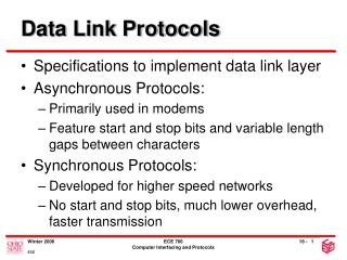
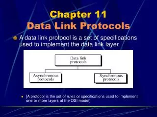
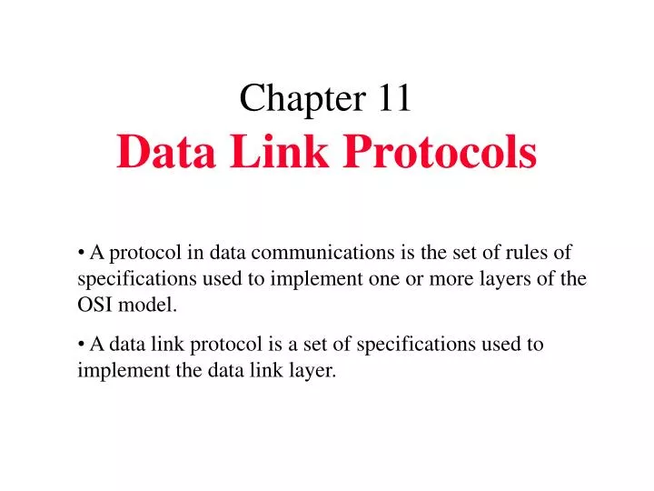
Chapter 11 Data Link Protocols. A protocol in data communications is the set of rules of specifications used to implement one or more layers of the OSI model. A data link protocol is a set of specifications used to implement the data link layer.

E N D
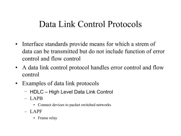
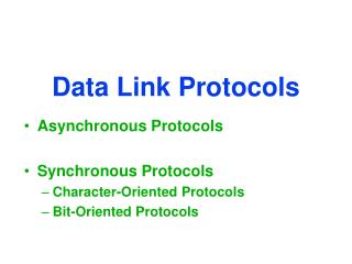
Chapter 11Data Link Protocols • A protocol in data communications is the set of rules of specifications used to implement one or more layers of the OSI model. • A data link protocol is a set of specifications used to implement the data link layer.
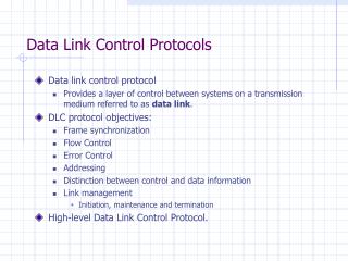
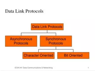
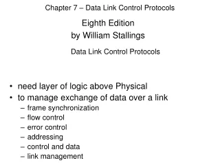
All bit-oriented protocols are related to high-level data link control (HDLC), a bit-oriented protocol published by ISO. HDLC supports both half-duplex and full-duplex modes in point to point and multipoint configurations. • System using HDLC can be characterized by their station types, their configurations, and their response modes.
Station in HDLC are of three types: Primary, secondary, and combined. A primary station send commands. A secondary station send responses. A combined station send commands and responses. • Configuration refer to the relationship of hardware devices on a link. Primary, secondary, and combined station can be configured in three ways: Unbalanced, symmetrical, and balanced.
Figure 11-14 HDLC Configuration
Figure 11-14-continued HDLC Configuration
Figure 11-14-continued HDLC Configuration
Figure 11-15 HDLC Modes NRM: A secondary device must have permission from the primary device before transmitting. ARM: A secondary may initiate a transmission without permission from the primary. ABM: All station arer equal and therefore only combined station connected in point to point are used.
Figure 11-16 HDLC Frame Types I-Frames are used only to transport control information, relating to user data.
Figure 11-16-continued HDLC Frame Types S-Frames are used only to transport control information, primarily data link layer flow and error controls.
Figure 11-16-continued HDLC Frame Types U-Frames are reserved for system management.
Figure 11-17 HDLC Flag Field
Bit Stuffing • Bit stuffing is the process of adding one extra 0 whenever there there are five consecutive 1s in the data so that the reciver does not mistake the data for a flag. Data sent 000111111001111101000 Frame sent Flag Address Control 000111110110011111001000 FCS Flag Frame Received Flag Address Control 000111110110011111001000 FCS Flag 000111111001111101000 Data Revived
Figure 11-18 Bit Stuffing 011111111000 0111110111000
Figure 11-19 HDLC Address Field If a primary station creates frame,it contains a to address.If a secondary creates the frame, it contains a from address
Figure 11-20 HDLC Control Field
Figure 11-21 Poll/Final
Figure 11-22 HDLC Information Field
Figure 11-23 HDLC FCS Field
Figure 11-25 Use of P/F Field
Figure 11-25-continued Use of P/F Field
Figure 11-25-continued Use of P/F Field
Figure 11-25-continued Use of P/F Field
Use of P/F Field Figure 11-25-continued
Figure 11-26 U-Frame Control Field Unnumbered frames are used to exchange session management and control information b/w connected devices. U-frame contain an information field, but one used for system management information not user data.
Figure 11-26-continued U-Frame Control Field
Figure 11-27 Polling Example
Selecting Example Figure 11-28
Peer-to-Peer Example Figure 11-29
Peer-to-Peer Example Figure 11-29-continued
Link Access Procedures LAPB LAPD LAPM • LAPB is used only in balanced configurations of two devices, where both devices are of the combined type. (ISDN). • LAPD It is used for out of band (control) signaling. • LAPM It is design to do asynchronous-synchronous conversion, error detection and retransmission.