Download
1 / 29
290 likes | 592 Views
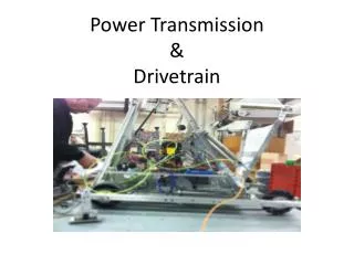
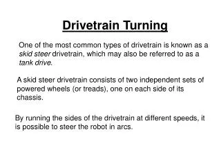
Advanced Drivetrain Calculations. John E. V-Neun, Team 229 John A. Neun, P.E., Team 20. Goals for this Session. Foundation for Gearbox Design Review principles in drivetrain design Examine trade-offs Formulas for modeling and design Sample Calculation. Prerequisites.

E N D
Advanced Drivetrain Calculations John E. V-Neun, Team 229 John A. Neun, P.E., Team 20
Goals for this Session Foundation for Gearbox Design • Review principles in drivetrain design • Examine trade-offs • Formulas for modeling and design • Sample Calculation
Prerequisites • Assume basic familiarity with: • Principles of Physics and Calculus • Forces, Power, Torque, Acceleration, Friction, Rotational vs. Linear Motion • Principles of DC Motors • Principles of Gear Trains • Ken and Paul’s seminar
Gearbox Design Process First, choose “Motion” Objective: Robot Speed 13 fps, full speed within 10 feet • Pick motor • (load vs amps) • Pick wheel config. • no. of wheels • material • diameter • Motor running • characteristics • Max torque per • current limit • Determine maximum • drive train load from • “wall push” Calculate required gear ratio from motor and output torques Calculate speed & acceleration Running characteristics Current limits Iterate
Transmission Goal: Translate Motor Motion and Power into Robot Motivation • Motor • Speed (rpm) • Torque • Robot • Speed (fps) • Weight
First AnalysisPushing against a wall… • Objective: Determine maximum load limit • System must withstand max load • Run continuously under maximum load • Not overload motors • Not overload circuit breakers • (Not break shafts, gears, etc.) • Suboptimum – ignore limit (risk failure)
Gear Ratio Robot Weight Motor specs Frictional coef. Speed acceleration Pushing against a wall… • Known Factors: • Motor Usage • Motor Characteristics • Wheel Friction • Max Motor Load (at 40 amps) • Solve For: • Required Gear Ratio
TL = Torque from load IM = Maximum current draw (motor limit) Ts = Stall torque IF = Motor free current IS = Motor stall current Max Motor Load
stall Free speed Calculate the Max Motor Load
Calculate the Gearbox LoadFind Required Gearbox Ratio Weight no. of wheels • Friction between wheel and carpet acts as a “brake”, and provides gearbox load. • Find torque load per gearbox. • Now Solve for Required Gear Ratio Frictional force
Check Robot Speed • How fast will the robot go with this required gear ratio? • Remember Units!!!
Is this fast enough? • Major Design Compromise… • Is this speed fast enough? • No? • Decrease Gearbox Load • Increase Gearbox Power • Live with the low speed… • Design two speeds! • Low speed/high force • High speed/low force • Risk failure • Design is all about tradeoffs
Secondary AnalysisPlotting Acceleration • Calculate Motor Current Draw and Robot Velocity over time (during robot acceleration). • Time to top speed • Important to show how drivetrain will perform (or NOT perform!) • If a robot takes 50 feet to accelerate to top speed, it probably isn’t practical!
Plotting Acceleration • Voltage to resting motor • Start at stall condition (speed = 0) • Stall torque initial acceleration • Robot accelerates • Motor leaves stall condition • Force decreases as speed increases.
Instantaneous Motor Torque • When Motor RPM = 0, Output Torque = Stall Torque • When Motor RPM = free speed Output Torque = 0 (in theory) • (.81)
Instantaneous Acceleration and Velocity • Instantaneous Acceleration (dependant on robot velocity, as seen in previous equations). • The instantaneous velocity can be numerically calculated as follows: (thanks, Isaac)
Velocity vs. Time • The numerical results can be plotted, as shown below (speed vs. time):
Current Draw Modeling • The current drawn by a motor can be modeled vs. time too. • Current is linearly proportional to torque output (torque load) of the motor.
Current Draw vs. Time • The numerical results can be plotted, as shown below:
What does this provide? • Based on these plots, one can see how the drivetrain will perform. • Does current draw drop below “danger” levels in a short time? • How long does it take robot to accelerate to top speed?
Are things okay? NO?!? • How can performance be increased? • Increase Drivetrain Power • Use Stronger Motors • Use Multiple Motors • Increase Gear Ratio (Reduce top speed) • Is this acceptable?
Adding Power – Multiple Motors • Combining Motors Together – Not Voodoo! • 2 Motors combine to become 1 “super-motor” • Match motors at free speed. • Sum all characteristics • Motor Load is distributed proportional to a ratio of free speed. • 2 of the same motor is easy! • 4 Chiaphua Motors
Multiple Speed Drivetrains • Allows for one “pushing” gear, and one “cruising” gear. • Shift on the fly allows for accelerating through multiple gears to achieve high speeds. • Shifting optimizes motor power for application at hand.
The big picture… • These calculations are used to design a competition drivetrain. • Rather than do them by hand, most designers use some kind of tool. • Excel Spreadsheet • Matlab Script • Etc…
And then… • This is a starting point • Iterate to optimize results • Test • Use your imagination • Infinite speeds • Multiple motors • Many gears • This isn’t the “end all” method.
Gearbox Design Process Set “Motion” Objective: Robot Speed 13 fps, full speed within 10 feet • Pick motor • (load vs amps) • Pick wheel config. • no. of wheels • material • diameter • Motor running • characteristics • Max torque per • current limit • Determine maximum • drive train load from • “wall push” Calculate required gear ratio from motor and output torques Calculate speed & acceleration Running characteristics Current limits Iterate
Demonstration • Here is an example of how to use a spreadsheet to do drivetrain design. • www.team229.org • Everything is available (or soon will be) in resources section of 229 web site