Download
1 / 44
440 likes | 559 Views
Thank You Sponsors. Baja Hybrid Drivetrain Design P14224. Thank You Sponsors. Problem Statement Identification of Critical Subsystems Identification of Vehicle States Analysis of Vehicle States Mechanical Subsystems Electrical Subsystems Mechanical Subsystem Interfaces Test Plan Update

E N D
Thank You Sponsors Baja Hybrid Drivetrain DesignP14224
Thank You Sponsors Problem Statement Identification of Critical Subsystems Identification of Vehicle States Analysis of Vehicle States Mechanical Subsystems Electrical Subsystems Mechanical Subsystem Interfaces Test Plan Update Budget Update Agenda
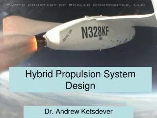
The RIT Baja Team has expressed an interest in improving drivetrain efficiency and dynamic control. The drivetrain has not had a significant format change since the 90’s, using a single speed reduction box coupled with a CVT. While this has been and continues to be an effective means of transmitting power to the wheels, and is the preferred solution amongst the top performing teams, the team would like to explore other options; specifically a gas-electric design. The team would like to receive a working bench top prototype of the drive system for the purpose of testing the gas electric system to compare it to the existing system. Problem Statement
Engine and Alternator Mounting • CR 3, 5 • ER 5, 15, 19 • DR 18, 19 • Wheel and Traction Motor Mounting • CR 5, 6 • ER 12, 14, 17, 19 • DR 20 Critical Subsystems - Mechanical
Controller • Engine System • Motor System • Accumulator System • Temperature • User Input Critical Subsystems - Electrical
CR 1, 2, 4, 5 • ER 9, 10, 11, 12 • DR 16, 17 Electrical – Engine System
CR 2, 4, 6, 13 • ER 11, 12, 17 • DR 1 - 7 Electrical – Motor System
CR 10, 13, 14 • ER 5, 13, 14, 16 Electrical – Accumulator System
CR 15 • ER 6, 7 • DR 14, 15 Electrical - Temperature
CR 1, 2, 4, 11, 13, 16 • ER 5, 8, 9, 10, 13, 14, 21 • DR 16, 17 Electrical – User Input
Acceleration / Sled Pull / Mud Bog / Hill Climb • Taxi • Full Throttle/Accelerating • Braking • Maneuverability / S+T / Rock Crawl • Taxi • Acceleration • Braking • Cornering • Endurance • Taxi • Acceleration • Braking • Cornering • Constant Speed Race Event Breakdown
Vehicle at Rest • Engine Off • Engine On • Cap bank full • Cap bank not full • Vehicle in Motion • *** Cap bank full/not full applies to all • Accelerating/Full Throttle • Coasting • Braking • Constant Speed • Taxi Vehicle States
At Rest, Engine Off • Mechanical • System loading at a minimum • Electrical • No electrical power flow
At Rest, Engine On, Cap Full • Mechanical • System loading at a minimum • Electrical • Alternator power in control closed • Power available for motor controller
At Rest, Engine On, Cap not Full • Mechanical • System loading at a minimum • Electrical • Alternator power in control open
Accelerating/Full Throttle • Mechanical • Maximum drive torque developed • Full tractive load • Electrical • All power is flowed to the motor controller • As voltage of system drops capacitorbank releases extra energy slowing the voltage fall
Coasting, Cap Full • Mechanical • Driveline in motion, but minimum loading • Electrical
Coasting, Cap not Full • Mechanical • Driveline in motion, but minimum loading • Electrical • Regen power used to charge cap bank
Braking, Cap Full • Mechanical • Maximum drive torque developed • Full tractive load • Electrical
Braking, Cap not Full • Mechanical • Maximum drive torque developed • Full tractive load • Electrical • Accumulator in charge state
Constant Speed, Cap Full • Mechanical • Intermediate drive torque developed • Intermediate tractive load • Electrical • Alternator supplies all necessary power to drive motor (engine may be revved down to conserve gas)
Constant Speed, Cap not Full • Mechanical • Intermediate drive torque developed • Intermediate tractive load • Electrical • Extra power diverted to cap bank charging
Accumulator System (Small Scale Results) Accumulator Steadily Charging Accumulator Steadily Discharging
Accumulator System High-side driver applied to accumulator system circuitry
Accumulator System Accumulator software flow diagram
Mechanical Test Plan • Traction motor selection • Receive torque information for RR selection • Begin cart design • Begin Sub frame design • Concept motor cooling • Reduction ratio range selection Test Plan Update Electrical Test Plan • Select microprocessor • Begin controller board layout • Concept motor cooling control • Continue software development • Continue development of accumulator control circuitry • Test: • Accumulator control circuitry • Encoder inputs • Servo control and power • Update bill of materials
Appendix Figure Customer requirements
Appendix Figure Engineering requirements
Appendix Figure Developed requirements