Download
1 / 65
660 likes | 844 Views
Robot Chassis and Drivetrain Fundamentals. Andy Baker, Team 45 John Neun, Team 20. 2006. I am not John V-Neun (sorry!) John Neun Senior Development Engineer Albany International Mentor on team 20, the Rocketeers. Andy Baker. TechnoKats team leader (#45)

E N D
Robot Chassis and Drivetrain Fundamentals Andy Baker, Team 45 John Neun, Team 20 2006
I am not JohnV-Neun (sorry!)John NeunSenior Development Engineer Albany InternationalMentor on team 20, the Rocketeers
Andy Baker • TechnoKats team leader (#45) • Sr. Mechanical Engineer: Delphi Corporation • Co-Owner: AndyMark, Inc. (www.andymark.biz) • 2003 Championship Woodie Flowers Award Winner
What is most important? • Drive Base • Drive Base • Drive Base* * - stolen from Mr. Bill Beatty (team 71)
Objectives Review “Base” Design • Chassis • Structure • Geometry • Material • Examples • Drivetrain • Wheels • Motors • Transmissions • Examples
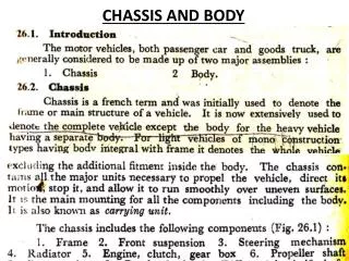
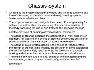
Chassis Design • Review principles of chassis design • Examine trade-offs • Material • Weight
Chassis Function • Provide platform for everything • Strong • Stable • Well laid out and accessible • Light • Resist, defend against shock
Weight • Develop a weight budget and stick to it! • Start coarse: chassis = 60 lbs, tower = 60 lbs • Tip: parts far from the floor should be the lightest • Refine: • ie Chassis • Frame • Wheels • Gearbox • Controls • Trade-off • How many ½ inch diameter holes in .100 Al are needed for 1 pound? 200!
d CG • Keep it Low!! spreadsheet
Geometry • Strength • Space • Accessibility
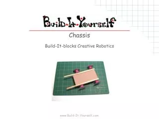
Kit Chassis (pictures available at www.innovationfirst.org) • Advantages: lightweight, quick to build, uses standard parts • Disadvantages: may not fit your design, requires added structure (that will most likely be put on anyway)
T-slot style • Advantages: quick to build, standard parts, easy to create tension and to add fastening points • Disadvantages: heavy, expensive
Welded Aluminum Tube & Plate • Advantages: lightweight, strength, fits your design • Disadvantages: takes time, requires skill, non standard parts
Unique Drive Bases • Advantages: fits your design, unique • Disadvantages: takes much time, requires skill, non standard parts
Chassis Materials • Aluminum Extrusion • 1/16” – 1/8”: usable but will dent and bend • T-slot: use 1” sized profiles or higher • Aluminum plates and bars • 3/16” – ¼” used often • Plastic Sheet • Spans structures, provides bracing • Polycarbonate (LEXAN, etc.) NOT Acrylic (Plexiglas, etc.) • Wood • Lightweight and easy to use • Will splinter and fail but can be fixed • Steel Tube and Angle • Strong, but heavy, 1/16” wall thickness is plenty strong
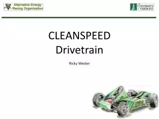
Drivetrain Design • Review basics • Examine trade-offs • Formulas for modeling and design • Sample Calculations
Drivetrain: #1 • What must the robot do? • Speed • Force • Maneuverability • Game rules and team strategy: set specs
Drivetrain Foundation Basics • Physics • Force = mass x acceleration (pounds) • Frictional force = constant x Normal force • Torque = force x distance (foot-pounds) • Power = force x velocity (HP, watts) = amps x volts • Work = power x time (HP-hour) • Efficiency = (power out)/(power in) • Principles of DC Motors • Principles of Gear Trains • Reduction • Mechanical advantage
Wheels • Provide contact with ground • Drive • Traction • Steering • Support and stability
Wheel Friction • Theory: F = kN • Frictional force has no dependence on contact area • HOMOGENEOUS, 2 dimensional surfaces • Drive direction vs. lateral friction N F
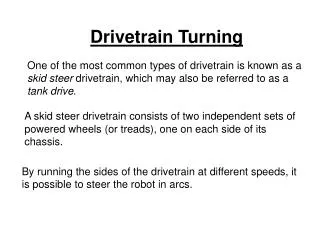
Steering wheels • “Car steering:” complex • “Tank steering:” simple • Wheels skate
Tank Steering • Hi CG • Short wheelbase • “Bouncy” wheels • Solutions: • Smaller Dia. Wheels • Use wider Frame (see Chris Hibner’s white paper on www.chiefdelphi.com) • Use Omni-wheels (www.andymark.biz)
6 Wheel Drive Teams can purchase these treaded wheels at… www.andymark.biz www.innovationfirst.com
Motors • Fixed population of choices • Range of speed and torque • Specifications readily available • DC motors with speed controlled via PWM • Last year’s motors: Use these numbers, but DON’T assume they are all true. For instance, the Fisher-Price motor could not be operated at 12 volts, and was later recommended to run at 6 volts.
TL = Torque from load IM = Maximum current draw (motor limit) Ts = Stall torque IF = Motor free current IS = Motor stall current Max Motor Load
stall Free speed Calculate the Max Motor Load Torque = Stall torque - {speed x (stall torque/free speed)}
Gearbox Design Process First, choose “Motion” Objective: Robot Speed 13 fps, full speed within 10 feet • Pick motor • (load vs amps) • Pick wheel config. • no. of wheels • material • diameter • Motor running • characteristics • Max torque per • current limit • Determine maximum • drive train load from • “wall push” Calculate required gear ratio from motor and output torques Calculate speed & acceleration Running characteristics Current limits Iterate
Transmission Goal: Translate Motor Motion and Power into Robot Motivation • Motor • Speed (rpm) • Torque • Robot • Speed (fps) • Weight
First Step: Pushing against a wall… • Objective: Determine maximum load limit (breakaway load for wheels) • System must withstand max load • Run continuously under maximum load • Not overload motors • Not overload circuit breakers • (Not break shafts, gears, etc.) • Suboptimum – ignore limit (risk failure)
Gear Ratio Robot Weight Motor specs Frictional coef. Speed acceleration Pushing against a wall… • Known Factors: • Motor Usage • Motor Characteristics • Wheel Friction • Max Motor Load (at 40 amps) • Solve For: • Required Gear Ratio
Calculate the Gearbox LoadFind Required Gearbox Ratio Weight no. of wheels • Friction between wheel and carpet acts as a “brake”, and provides gearbox load. • Find torque load per gearbox. • Now Solve for Required Gear Ratio Frictional force
Check Robot Speed • How fast will the robot go with this required gear ratio? • Remember Units!!!
Is this fast enough? • Major Design Compromise… • Is this speed fast enough? • No? • Decrease Gearbox Load • Increase Gearbox Power • Live with the low speed… • Design two speeds! • Low speed/high force • High speed/low force • Risk failure • Design is all about tradeoffs
Secondary AnalysisPlotting Acceleration • Calculate Motor Current Draw and Robot Velocity over time (during robot acceleration). • Time to top speed • Important to show how drivetrain will perform (or NOT perform!) • If a robot takes 50 feet to accelerate to top speed, it probably isn’t practical! • Performance on flat floor is VASTLY different on a ramp (2003 example)
Plotting Acceleration • Voltage to resting motor • Start at stall condition (speed = 0) • Stall torque initial acceleration • Robot accelerates • Motor leaves stall condition • Force decreases as speed increases.
Instantaneous Motor Torque • When Motor RPM = 0, Output Torque = Stall Torque • When Motor RPM = free speed Output Torque = 0 (in theory) • (.81)
Gearbox (reduction) basics N2 • Chain, belt • Gear Ratio = N2/N1 • Spur gears • Gear Ratio = N2/N1 N1 N2 N1
Instantaneous Acceleration and Velocity • Instantaneous Acceleration (dependant on robot velocity, as seen in previous equations). • The instantaneous velocity can be numerically calculated as follows: (thanks, Isaac)
Velocity vs. Time • The numerical results can be plotted, as shown below (speed vs. time):
Current Draw Modeling • The current drawn by a motor can be modeled vs. time too. • Current is linearly proportional to torque output (torque load) of the motor.