Download

1 / 12
140 likes | 565 Views
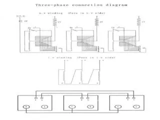
Transformer -2. (d) Tapped -windings. ( a) Iron-cored Transformer. F. B. E. D. A. C. (b) Ferrite –cored Transformer. (e) Auto-Transformer. C. B. A. (c) Multiple-windings. H. G. B. F. E. A. D. C. Types of transformer. Construction of transformer.

E N D
(d) Tapped -windings (a) Iron-cored Transformer F B E D A C (b) Ferrite –cored Transformer (e) Auto-Transformer C B A (c) Multiple-windings H G B F E A D C Types of transformer
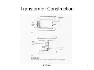
Construction of transformer Laminated steel-core transformer
6000/230 V I1 R1 Xe R2 I2 10 23 0.016 V1 V1’ V2’ V2 30 kVA Example 5 Primary windings of a 30 kVA, 6000 V/230 V transformer has a resistance of 10 , the secondary windings has a resistance of 0.016 . The total reactance of the transformer referred to primary is 23 . Calculate the voltage regulation of the transformer when it supplies a the full-load current at power factor of 0.8 lagging
I1 Re Xe 6000/230 V I2 V1 V1’ V2’ V2 30 kVA Equivalent resistance of primary and secondary referred to primary is Full-load current at primary
Efficiency • Losses in transformer on load categorized into two • I2R losses in primary and secondary windings, namely I12R1+I22R2. • Core losses due to hysteresis and eddy currents Usually variation between no-load and full-load can be negligible thus, the total core loss, PC , is assumed to be constant all the time. Therefore total loss or R1e=equivalent resistance of primary and secondary referred to primary R2e=equivalent resistance of primary and secondary referred to secondary
Note: p.f= power factor The wire losses can be expressed as Divided by I2
Example 6 The primary and secondary windings of a 500 kVA transformer have a resistances of 0.42 and 0.0011 respectively. The primary and secondary voltages are 6600 V and 400 V respectively and the core loss is 2.9 kW , assuming the power factor of the load to be 0.8. Calculate the efficiency on (a) full-load and (b) half-load. (c) assuming the power factor 0.8, find output which the efficiency of the transformer is maximum. (a) Primary current on full-load Secondary current on full-load Coil Wire loss at primary PW1=I12R1=75.82 x 0.42=2415W Coil Wire loss at secondary PW2=I22R2=12502 x 0.0011=1720W
PW = PW1 + PW2 = 2415 + 1720 = 4.135kW Total loss PL= PW + PC = 4.135 + 2.9 = 7.035kW Output power on full load Pout = 500 x 0.8 = 400 kW Therefore Pin = Pout + PL = 400+7.035 = 407.035 kW
(b) Since the wire loss varies as square of the current , thus Losses on half-load PW/2=4.135/22=4.135/4=1.034kW Total Loss on half-load PL= PC+PW/2=2.9+1.034=3.934kW Output power on half-load Pout/2= 400/2 = 200kW Input power on half-load Pin/2= Pout/2+PL=200+3.934 = 203.934kW
(c) Full-load I2R loss is PW = 4.135kW Let n= fraction of full-load appearance power at which it is maximum efficiency Total I2R loss is = n2 x 4.135 kW=2.9 Therefore n=0.837 Output at maximum efficiency is= 0.837 x 500= 418.5kWA Output power at power factor 0.8= 418.5 x 0.8 = 334.8 kWA Since the core and I2R are equaled, then total loss is PL= 2 x 2.9 = 5.8 kW