Download
1 / 18
200 likes | 358 Views
TRANSFORMER. What is Transformer?. Transformer is an A.C. device used to change high voltage low current A.C. into low voltage high current A.C. and vice-versa without changing the frequency In brief, 1. Transfers electric power from one circuit to another

E N D
What is Transformer? Transformer is an A.C. device used to change high voltage low current A.C. into low voltage high current A.C. and vice-versa without changing the frequency In brief, 1. Transfers electric power from one circuit to another 2. It does so without a change of frequency 3. It accomplishes this by electromagnetic induction 4. Where the two electric circuits are in mutual inductive influence of each other.
Principle of operation It is based on principle of MUTUAL INDUCTION. According to which an e.m.f. is induced in a coil when current in the neighbouring coil changes.
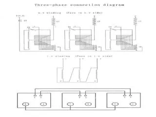
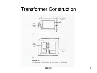
Constructional detail : Shell type • Windings are wrapped around the center leg of a laminated core.
Core type • Windings are wrapped around two sides of a laminated square core.
Shell type • The HV and LV windings are split into no. of sections • Where HV winding lies between two LV windings • In sandwich coils leakage can be controlled Fig: Sandwich windings
Working of a transformer 1. When current in the primary coil changes being alternating in nature, a changing magnetic field is produced 2. This changing magnetic field gets associated with the secondary through the soft iron core 3. Hence magnetic flux linked with the secondary coil changes. 4. Which induces e.m.f. in the secondary.
Ideal Transformers • Zero leakage flux: -Fluxes produced by the primary and secondary currents are confined within the core • The windings have no resistance: - Induced voltages equal applied voltages • The core has infinite permeability - Reluctance of the core is zero - Negligible current is required to establish magnetic flux • Loss-less magnetic core - No hysteresis or eddy currents
Transformer Tests • The performance of a transformer can be calculated on the basis of equivalent circuit • The four main parameters of equivalent circuit are: • - R01 as referred to primary (or secondary R02) • - the equivalent leakage reactance X01as referred to primary (or secondary X02) • - Magnetising susceptance B0 ( or reactance X0) • - core loss conductance G0 (or resistance R0) • The above constants can be easily determined by two tests • - Oper circuit test (O.C test / No load test) • - Short circuit test (S.C test/Impedance test) • These tests are economical and convenient • - these tests furnish the result without actually loading the transformer Electrical Machines
Open-circuit Test In Open Circuit Test the transformer’s secondary winding is open-circuited, and its primary winding is connected to a full-rated line voltage. • Usually conducted on H.V side • To find (i) No load loss or core loss (ii) No load current Io which is helpful in finding Go(or Ro ) and Bo (or Xo )
Short-circuit Test In Short Circuit Test the secondary terminals are short circuited, and the primary terminals are connected to a fairly low-voltage source The input voltage is adjusted until the current in the short circuited windings is equal to its rated value. The input voltage, current and power is measured. • Usually conducted on L.V side • To find (i) Full load copper loss – to pre determine the efficiency (ii) Z01 or Z02; X01 or X02; R01 or R02 - to predetermine the voltage regulation
Transformer Voltage Regulation and Efficiency The output voltage of a transformer varies with the load even if the input voltage remains constant. This is because a real transformer has series impedance within it. Full load Voltage Regulation is a quantity that compares the output voltage at no load with the output voltage at full load, defined by this equation: Ideal transformer, VR = 0%. Electrical Machines
Voltage regulation of a transformer recall Secondary voltage on no-load V2 is a secondary terminal voltage on full load Substitute we have
Transformer Efficiency Transformer efficiency is defined as (applies to motors, generators and transformers): • Types of losses incurred in a transformer: • Copper I2R losses • Hysteresis losses • Eddy current losses • Therefore, for a transformer, efficiency may be calculated using the following: Electrical Machines
Losses in a transformer Core or Iron loss: Copper loss: