Download
1 / 32
320 likes | 431 Views
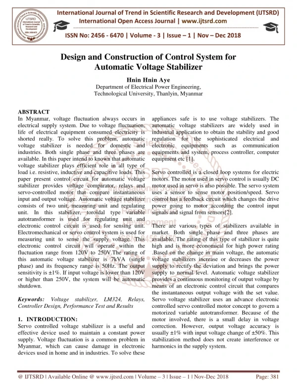
A System for Automatic Recording and Prediction of Design Quality Metrics. Andrew B. Kahng and Stefanus Mantik* UCSD CSE and ECE Depts., La Jolla, CA *UCLA CS Dept., Los Angeles, CA. Introduction. Time-to-market window is shrinking very rapidly

E N D
A System for Automatic Recording and Prediction of Design Quality Metrics Andrew B. Kahng and Stefanus Mantik* UCSD CSE and ECE Depts., La Jolla, CA *UCLA CS Dept., Los Angeles, CA
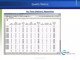
Introduction • Time-to-market window is shrinking very rapidly • Product quality and design process must continually improve • Currently, there are no standards or infrastructure for measuring and recording the semiconductor design process • METRICS provides • Standard infrastructure for the collection and the storage of design process information • Standard list of design metrics and process metrics • Analyses and reports that are useful for design process optimization • METRICS allows: Collect, Data-Mine, Measure, Diagnose, then Improve
Related Works • Enterprise- and project-level metrics (“normalized transistors”) Numetrics Management Systems DPMS • Other in-house data collection systems • e.g., TI (DAC 96 BOF), OxSigen LLC (Siemens Semiconductor) • Design Process Management [Jacome93, Brockman92, Johnson96] • Web-based design support • IPSymphony, WELD, VELA, etc. • Continuous process improvement • Data mining and visualization
Outline • METRICS system architecture and standards • METRICS for design flow • Flow METRICS experiments • METRICS integration with datamining • Datamining integration experiments • Issues and conclusions
Tool Tool Transmitter Java Applets wrapper Tool API Transmitter Transmitter XML Inter/Intra-net Web Server Data Mining DB Reporting Metrics Data Warehouse METRICS System Architecture
Generic and Specific Tool Metrics Partial list of metrics now being collected in Oracle8i
Outline • METRICS system architecture and standards • METRICS for design flow • Flow METRICS experiments • METRICS integration with datamining • Datamining integration experiments • Issues and conclusions
Flow Metrics • Tool metrics alone are not enough • Design process consists of more than one tool • A given tool can be run multiple times • Design quality depends on the design flow and methodology (the order of the tools and the iteration within the flow) • Flow definition • Directed graph G (V,E) • V T { S, F } • T { T1, T2, T3, …, Tn } (a set of tasks) • S starting node, F ending node • E { Es1, E11, E12, …, Exy } (a set of edges) • Exy • x < y forward path • x = y self-loop • x > y backward path
S T1 T1 T1 T2 T2 T2 T2 T3 T3 T3 T4 T4 F Flow Example S T1 T2 T3 Optional task T4 F Task sequence: T1, T2, T1, T2, T3, T3, T3, T4, T2, T1, T2, T4
S T1 T1 T1 T2 T2 T2 T2 T3 T3 T3 T4 T4 F Flow Tracking Task sequence: T1, T2, T1, T2, T3, T3, T3, T4, T2, T1, T2, T4
NELSIS Flow Manager Integration • Flow managed by NELSIS Snap shot of NELSIS
Optimization of Incremental Multilevel FM Partitioning • Motivation: Incremental Netlist Partitioning • netlist ECOs are made; want top-down placement to remain similar to previous result • good approach [CaldwellKM00]: “V-cycling” based multilevel Fiduccia-Mattheyses • what is the best tuning of the approach for a given instance? • break up the ECO perturbation into multiple smaller perturbations? • #starts of the partitioner? • within a specified CPU budget?
... T1 T2 T3 Tn S F Optimization of Incremental Multilevel FM Partitioning (contd.) • Given: initial partitioning solution, CPU budget and instance perturbations (I) • Find: number of parts of incremental partitioning and number of starts • Ti = incremental multilevel FM partitioning • Self-loop multistart • n number of breakups (I = 1 + 2 + 3 + ... + n)
Multilevel FM Experiment Flow Setup foreachtestcase foreachI foreachCPUbudget foreachbreakup Icurrent = Iinitial Scurrent = Sinitial fori = 1 ton Inext = Icurrent + i run incremental multilevel FM partitioner on Inext to produce Snext ifCPUcurrent > CPUbudgetthen break Icurrent = Inext Scurrent = Snext end
Predicted CPU Time (secs) Actual CPU Time (secs) Flow Optimization Results • If (27401 < num edges 34826) and (143.09 < cpu time 165.28) and (perturbation delta 0.1) then num_inc_parts = 4 and num_starts = 3 • If (27401 < num edges 34826) and (85.27 < cpu time 143.09) and (perturbation delta 0.1) then num_inc_parts = 2 and num_starts = 1 • ...
Identifying the Effect of Wire Load Model • Wire load model (WLM) is used for pre-layout estimation of wire delays • Three different WLMs • statistical WLM • structural WLM • custom WLM • Motivation: • identify if WLMs are useful for estimation • identify if WLMs are necessary for optimization • identify the best role of WLMs
S T1 T2 T3 T4 T5 T6 T7 T8 F Wire Load Model Flow • WLM flows for finding the appropriate role of WLM • T1 = synthesis & technology mapping • T2 = load wire load model (WLM) • T3 = pre-placement optimization • T4 = placement • T5 = post-placement optimization • T6 = global routing • T7 = final routing • T8 = custom WLM generation
WLM Experiment Setup foreachtestcase foreachWLM (statistical, structural, custom, and no WLM) foreach flow variant run PKS flow ifWLM = structuralthen generate custom WLM end 6 different flow variants
WLM Flow Results Slack comparison for 6 flow variants • Post-placement and pre-placement optimizations are important steps • Choice of WLM depends on the design
Outline • METRICS system architecture and standards • METRICS for design flow • Flow METRICS experiments • METRICS integration with datamining • Datamining integration experiments • Issues and conclusions
Java Servlet Java Servlet Datamining Integration Inter-/Intranet DM Requests SQL Results Tables Database Datamining Interface Datamining Tool(s) Tables Tables SQL Results
Categories of Data for DataMining • Design instances and design parameters • attributes and metrics of the design instances • e.g., number of gates, target clock frequency, number of metal layers, etc. • CAD tools and invocation options • list of tools and user options that are available • e.g., tool version, optimism level, timing driven option, etc. • Design solutions and result qualities • qualities of the solutions obtained from given tools and design instances • e.g., number of timing violations, total tool runtime, layout area, etc.
Possible Usage of DataMining • Design instances and design parameters • CAD tools and invocation options • Design solutions and result qualities • Given and , estimate the expected quality of • e.g., runtime predictions, wirelength estimations, etc. • Given and , find the appropriate setting of • e.g., best value for a specific option, etc. • Given and , identify the subspace of that is “doable” for the tool • e.g., category of designs that are suitable for the given tools, etc.
Example Applications with DM • Parameter sensitivity analysis • input parameters that have the most impact on results • Field of use analysis • limits at which the tool will break • tool sweet spots at which the tool will give best results • Process monitoring • identify possible failure in the process (e.g., timing constraints are too tight, row utilization is too high, etc.) • Resource monitoring • analysis of resource demands (e.g., disk space, memory, etc.)
Predicted CPU Time (secs) Actual CPU Time (secs) DM Results: QPlace CPU Time • If (num nets 7332) then CPU time = 21.9 + 0.0019 num cells + 0.0005 num nets + 0.07 num pads - 0.0002 num fixed cells • If (num overlap layers = 0) and (num cells 71413) and (TD routing option = false) then CPU time = -15.6 + 0.0888 num nets - 0.0559 num cells - 0.0015 num fixed cells - num routing layer • ...
Selection for Training and Test Sets • Random Case • randomly select runs assigned to training set • leave all remained (unselected) runs for test set • Distinct Case • split the test cases into two distinct sets, the training set and the test set • assign the runs accordingly • Representative Case • split the test cases into two distinct sets and assign the runs accordingly • for each test case in the test set, move exactly one run to the training set • I.e., for each test case, there is at least one representative run in the training set
Prediction Result Variances Random Case Distinct Case Representative Case Prediction of QP Wirelength
CTGen Results Max Insertion Delay (ns) Min Insertion Delay (ns) Max Skew
Outline • METRICS system architecture and standards • METRICS for design flow • Flow METRICS experiments • METRICS integration with datamining • Datamining integration experiments • Issues and conclusions
Conclusions • Extensions to current METRICS system is presented • Complete prototype of METRICS system is working at UCLA with Oracle8i, Java Servlet and XML (other working prototypes are installed at Intel and Cadence) • METRICS wrapper for Cadence and Cadence-UCLA flows, front-end tools (Ambit BuildGates and NCSim) • METRICS system is integrated with Cubist datamining tool and NELSIS flow manager • A complete METRICS system can be installed on a laptop and configured to work behind firewalls
Issues and Ongoing Work • Issues for METRICS constituencies to solve • security: proprietary and confidential information • standardization: flow, terminology, data management, etc. • social: “big brother”, collection of social metrics, etc. • Ongoing work with EDA, designer communities to identify tool metrics of interest • users: metrics needed for design process insight, optimization • vendors: implementation of the metrics requested, with standardized naming / semantics
Thank You http://vlsicad.cs.ucla.edu/GSRC/METRICS