Download
1 / 52
560 likes | 1.24k Views
Energy concept for future oil refineries with an emphasis on separation processes. Antonio Carlos Brandão de Araújo Department of Chemical Engineering Norwegian University of Science and Tecnology (NTNU) Trondheim, Norway January 2007. About this presentation. Motivation:

E N D
Energy concept for future oil refineries with an emphasis on separation processes Antonio Carlos Brandão de Araújo Department of Chemical Engineering Norwegian University of Science and Tecnology (NTNU) Trondheim, Norway January 2007
About this presentation • Motivation: • Focus on environmental aspects in oil refining is not enough ([Szklo 2007], [DOE 2000]). • Energy-efficient processes in oil refining are paramount. • Need for research in this field is a must. • Focus: • What’s up on the future of energy consumption. • Opportunities: I’ll give directions. • Looking at the big picture: Not restricted to separation processes. • Goal: • Attempting to show what one can expect in terms of more energy-efficient refineries.
About this presentation Energy concept = Energy efficiency. Keep it simple! • Let’s tear things down: Directions will be given but problems wont’t be solved here! Catalytic cracking + separation unit Energy concept for future refineries. Future = Next 20 years. Nothing futuristic! No revolution! • Directions will be given… Well, it cannot be different since there are lots of alternatives to consider and details cannot be given here!
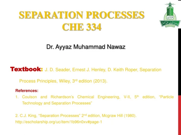
Outline • A vision for the future • A simple guide to oil refining • Energetic issues in an oil refinery • Thermodynamic analysis and measures to improve energy consumption. • Crude oil distillation (atmospheric and vacuum) • Fluid catalytic cracking • Catalytic hydrotreating • Catalytic reforming • Alkylation • Separation processes • Recap and future directions • References
A vision for the future • According to the API’s Technology Vision 2020: A Technology Vision for the U.S. Petroleum Refining Industry [API 2000] report, • The petroleum industry of the future will be environmentally sound, energy-efficient, safe and simpler to operate. It will be completely automated, operate with minimal inventory, and use processes that are fundamentally well-understood. Over the long term, it will be sustainable, viable, and profitable, with complete synergy between refineries and product consumers. • To improve energy and process efficiency, the industry will strive to use cost-effective technology with lower energy-intensity. Refineries will integrate state-of-the-art technology (e.g., separations, catalysts, sensors and controls, biotechnology) to leapfrog current refinery practice and bring efficiency to new levels.
Outline • A vision for the future • A simple guide to oil refining • Energetic issues in an oil refinery • Thermodynamic analysis and measures to improve energy consumption. • Crude oil distillation (atmospheric and vacuum) • Fluid catalytic cracking • Catalytic hydrotreating • Catalytic reforming • Alkylation • Separation processes • Recap and future directions • References
A simple guide to oil refining • According to the North American Industry Classification System (NAICS) [DOE 2006], petroleum refineries are defined as: Establishments primarily engaged in refining crude petroleum into refined petroleum. Picture of the oil refinery of the future, if the oil consumption maintains its crazy growth… Actually, this is a 1876 oil refinery in California.
A simple guide to oil refining • In short: • Everything is upgraded to valuable products: More fuel! • Over 43% of production is gasoline. • Almost 80% is converted to fuel. • It is a huge process facility!!! • Lots of reactions and separations to add value to the product. • Many opportunities for energy savings.
Outline • A vision for the future • A simple guide to oil refining • Energetic issues in an oil refinery • Thermodynamic analysis and measures to improve energy consumption. • Crude oil distillation (atmospheric and vacuum) • Fluid catalytic cracking • Catalytic hydrotreating • Catalytic reforming • Alkylation • Separation processes • Recap and future directions • References
Energetic issues in an oil refinery ([DOE 2000], [Pellegrino 2005]) • Refinery gas + petroleum coke + other oil-based by-products accounts for 65% of the energy sources in an oil refinery. • 38% of the energy sources in an oil refinery are used to produce non-fuel products like lubricant oils, wax, asphalt, and petrochemical feedstocks. • Oil refineries generate large amounts of electricity on-site. In the U.S., over 40% (1994) of electricity in refineries are on-site generated. • The cost of energy for heat and power accounts for 40% of the operating costs in the refinery!!!
Energetic issues in an oil refinery [DOE 1998] • According to the NAICS, the petroleum refineries consumed 3.1 quadrillion Btu in 2002, almost 20% of the fuel energy consumed by the U.S.. • From the Table 35% is consumed in two distillation processes. • As expected, hydrotreating is also very high, 19% alone. • Units in circles are prone to be “optimized” energetically as they represent approx. 80% of the energy consumed by the refining process. • We will focus on these units.
Energetic issues in an oil refinery [Worrell 2005] • Hydrogen generation is yet another high energy consumption process. • Large amounts of energy are consumed as fuel, while the rest is basically steam.
Energetic issues in an oil refinery [DOE 2000] • Future characteristics of oil refineries in terms of energy use: • Energy use is optimized throughout the refinery complex. • Energy efficiency and process controls are integrated. • Fouling of heat exchangers is essentially eliminated. • Innovative heat exchangers are in place (all helical, vertical, no baffles) • Use of cogeneration in refineries is optimized, and refineries are power producers. • Use of very energy-intensive processes (e.g., distillation, furnaces) is minimized. • Source of heat loss (e.g., in pipes) are easily identified through monitoring. • How? • Identify entirely new technology. • Upgrade existing inefficient technology.
0-3 years 10-20 years 3-10 years Energetic issues in an oil refinery [DOE 2000] • Replacing the conventional energy-intensive separation processes has a tremendous impact on energy consumption. • Waste recovery in the short term. • Fouling mitigation and new refining processes in the mid and long terms. • Membrane is the first step. • Catalytic distillation is in the mid run. • Long run: distillation beyond membrane. • [Pelegrino 1999] say the target is 15-20% energy reduction for U.S. refineries.
Outline • A vision for the future • A simple guide to oil refining • Energetic issues in an oil refinery • Thermodynamic analysis and measures to improve energy consumption. • Crude oil distillation (atmospheric and vacuum) • Fluid catalytic cracking • Catalytic hydrotreating • Catalytic reforming • Alkylation • Separation processes • Recap and future directions • References
Thermodynamic analysis… [DOE 2006] • Remember the 5 processes with the largest energy consumption? • A thermodynamic analysis of these 5 processes is performed. • Three measures are defined: • TW = Theoretical Work: The least amount of energy that a process would require under ideal conditions. • CW = Current Work: Energy consumed under actual plant conditions. • PW = Practical Work: Minimum energy required to run the process in real-world, non-standard conditions by applying cutting edge technologies still on the drawing board. • By applying these state-of-the-art technologies the maximum potential for energy savings can be quantified by PI (Potential Improvement) = CW (Current Work) – PW (Practical Work)
Crude oil distillation (atmospheric and vacuum) • Atmospheric distillation: • It is the heart of the refinery. • It produces a range of products, from LPG to heavy crude residue. • High temperature (bottom 600oC), low pressure (near atmospheric) process. • Vacuum distillation: • It has heavy crude (high boiling point) as feedstock. • It must then be conducted at vacuum conditions. • It produces light and heavy gas oil and asphalt (or resid). • These products are upgraded.
Crude oil distillation (atmospheric and vacuum) • Atmospheric distillation energetic assessment [DOE 2006]: • Theoretical work = 22 x 103 Btu/bbl feed • Current work = 109 x 103 Btu/bbl feed • Practical work = 50 x 103 Btu/bbl feed • Potential improvement = 59 x 103 Btu/bbl feed • The potential improvement can be achieved by ([Gadalla 2003a], [Gadalla 2003b], [ANL 1999], [TDGI 2001], [Liporace 2005], [Seo 2000], [Rivero 2004], [Yeap 2005], [Hovd 1997], [Sharma 1999]) • Control of fouling in the crude preheat train and fired heater. • Improved heat integration between the atmospheric and vacuum towers. • Improved tray design and heat integration between trays, and optimization of the number of trays and operating conditions for improved vapor-liquid contact and higher throughput. • Enhanced cooling to lower overhead condenser cooling water from 75°F to 50°F. • Implementation of advanced control.
Crude oil distillation (atmospheric and vacuum) • Vacuum distillation energetic assessment [DOE 2006]: • Theoretical work = 46 x 103 Btu/bbl feed • Current work = 89 x 103 Btu/bbl feed • Practical work = 54 x 103 Btu/bbl feed • Potential improvement = 35 x 103 Btu/bbl feed • The potential improvement can be achieved by ([Gadalla 2003a], [Gadalla 2003b], [ANL 1999], [TDGI 2001], [Sharma 1999], [Liporace 2005], [Seo 2000], [Rivero 2004], [Yeap 2005]) • Control of fouling in the fired heater. • Improved heat integration between the atmospheric and vacuum towers. • Improved tray design and heat integration between trays, and optimization of the number of trays and operating conditions for improved vapor-liquid contact and higher throughput. • Enhanced cooling to lower overhead condenser cooling water from 75°F to 50°F. • Implementation of advanced control.
Fluid catalytic cracking • Objective: Convert heavy oils into more valuable gasoline and lighter products. • Feedstocks are light and heavy gas oil from atmospheric or vacuum distillation, coking, and deasphalting operations. High temperature, catalytic cracking reactions:
Fluid catalytic cracking • Energetic assessment [DOE 2006]: • Theoretical work = 40 x 103 Btu/bbl feed • Current work = 183 x 103 Btu/bbl feed • Practical work = 132 x 103 Btu/bbl feed • Potential improvement = 51 x 103 Btu/bbl feed • The potential improvement can be achieved by ([Linhoff 2002], [ANL 1999]) • Addition of a power recovery turbine. • Conversion of condensing turbine drive to electric motor drive (wet gas compressor). • Improved heat integration, pinch analysis. • Minimization of other miscellaneous losses.
Catalytic hydrotreating • Objective: Remove sulfur, nitrogen, and metals and upgrade heavy olefinic feed by saturation with hydrogen to produce paraffins. • It commonly appears in multiple locations in a refinery (5 or more of these units). • They are usually placed upstream of units where catalyst deactivation may occur. • Typically we can distinguish: Naphtha hydrotreater, kerosene hydrotreater, and gas oil hydrotreater. • Main reactions:
Catalytic hydrotreating • Energetic assessment [DOE 2006]: • Theoretical work = 30 x 103 Btu/bbl feed • Current work = 81 x 103 Btu/bbl feed • Practical work = 55 x 103 Btu/bbl feed • Potential improvement = 26 x 103 Btu/bbl feed • The potential improvement can be achieved by ([ANL 1999], [Gary 2001], [Linhoff 2002], [Liebmann 1998]) • Improved pre-heater performance. • Improved catalyst. • Improved heat integration, pinch analysis. • Minimization of other miscellaneous losses.
Catalytic reforming • Objective: Convert naphthas and heavy straight-run gasoline into high-octane gasoline blending components and hydrogen production. • It essentially restructures hydrocarbon molecules to increase the octane of motor gasoline. • Main reactions: • Dehydrogenation of naphthenes to aromatics: Methylcyclohexane → Toluene + 3H2 Methylcyclopentane → Cyclohexane → Benzene + 3H2 • Dehydrocyclization of paraffins to aromatics: n-Heptane → Toluene + 4H2 • Isomerization: n-Hexane → Isohexane Methylcyclopentane → Cyclohexane • Hydrocracking: n-Decane → Isohexane + nButane
Catalytic reforming • Energetic assessment [DOE 2006]: • Theoretical work = 79 x 103 Btu/bbl feed • Current work = 264 x 103 Btu/bbl feed • Practical work = 203 x 103 Btu/bbl feed • Potential improvement = 61 x 103 Btu/bbl feed • The potential improvement can be achieved by ([ANL 1999], [Gary 2001], [Packinox 2003]) • Improved feed and interstage process heater performance (e.g., improved convection section heat recovery). • Replace horizontal feed/effluent heat exchangers with vertical plate and frame exchanger. • Improved equipment efficiency (e.g., recycle and net gas compressor, reactor product air cooler). • Additional process cooling to improve light ends recovery (vapor compression vs. ammonia absorption). • Minimization of other miscellaneous losses.
Alkylation • Objective: Produce branched paraffins that are used as blending components in fuels to boost octane levels without increasing the fuel volatility. • There are two alkylation processes: sulfuric acid-based and hydrofluoric acid-based. • Both are low-temperature, low-pressure, liquid-phase catalyst reactions. • Main reaction:
Alkylation (H2SO4 process) • Energetic assessment [DOE 2006]: • Theoretical work = -58 x 103 Btu/bbl feed • Current work = 250 x 103 Btu/bbl feed • Practical work = 156 x 103 Btu/bbl feed • Potential improvement = 94 x 103 Btu/bbl feed • The potential improvement can be achieved by ([Gadalla 2003a], [TDGI 2001], [DOE 2006], [Schultz 2002]) • Improved compressor efficiency, from 25% to 50%. • Improved heat integration, pinch analysis. • Use of a dividing wall column design or other advanced separation technology. • Upgraded control system.
Summary • As expected, crude distillation (atmospheric and vacuum) has the largest potential for savings. • Followed by alkylation and catalytic treatments. • Note that separation sections are also included in the conversion processes. • As a general potential improvement, I particularly would also include assessment of the control structure design of the refinery.
Outline • A vision for the future • A simple guide to oil refining • Energetic issues in an oil refinery • Thermodynamic analysis and measures to improve energy consumption. • Crude oil distillation (atmospheric and vacuum) • Fluid catalytic cracking • Catalytic hydrotreating • Catalytic reforming • Alkylation • Separation processes • Recap and future directions • References
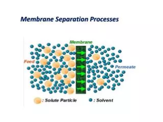
Separation processes • The majority of the available literature is related to the issue concerning distillation and they are heavily concentrated in the atmospheric and vacuum columns. I bet you know the reason! • Future solutions for improving energy efficiency in separation processes in oil refineries are basically related to: • Membrane technology. • Fouling mitigation. • Advanced process control and optimization. • Heat integration. • Design of efficient separation systems. • What follows are mostly on the drawing board, i.e., no real-world implementation.
Separation processes • Membrane technology: • [Wauquier 2000] discusses that membrane technology is still an infant in the world of grown-up inefficient processes in the oil industry. Its main application is in hydrodesulfurization processes in catalyst hydrotreating units, replacing existing separation processes with energy savings up to 20%. • Nevertheless, [Goulda 2001] and [White 2000] claimed a fuel reduction of 36,000 bbl/year (or 20% w.r.t. the conventional process) by adding a membrane unit in the dewaxing unit to recover part of the solvent stream. The membrane is selective to the solvent from the solvent/oil/wax mix. • According to [Szklo 2007], further research is needed to develop appropriate membrane materials that can withstand the harsh conditions in petroleum refining processes.
Separation processes • Fouling mitigation: • [Panchal 2000] presented a performance monitoring via an Excel® spreadsheet of the preheat train for a crude distillation unit. The authors claim that by using their technique the energy loss in a period of 2 years can be reduced by almost 60%. • [Nasr 2006] proposed a model of crude oil fouling in preheat exchangers with the aim of better controlling fouling formation. In contrast with other models, the one proposed by the authors consider the mechanisms of formation and natural removal. • [Yeap 2005] presented the application of existing fouling models to maximize heat recovery in the preheat train of the crude oil distillation. The authors’ conclusion was that designing for maximum heat recovery results in a less efficient system over time due to fouling effects. • However, [Szklo 2007] states that the very complex mechanisms which lead to fouling are still not properly understood to the extent they can be safely used for fouling mitigation techniques (anti-fouling agents and coatings).
Separation processes • Advanced process control and optimization: • [Domijan 2005] optimized a crude distillation unit by using a model that, according to the authors, has some advantages over commercial ones since it is adapted to real plant conditions, it is open source as well as flexible and fast. Moreover, it can also identify fouling level and be applied for planning shutdowns and maintenance stops. They claimed they found an optimal solution that saves up to 3.2% of energy consumption vis-à-vis actual operating conditions. • [Seo 2000] considered the optimal design of the crude distillation unit (atmospheric, vacuum, and naphtha stabilizer) by optimizing feed locations, heat duties of pumparounds and operating conditions of the preheat train. They use a MINLP framework. They claim the energy recovery in pumparounds and preheat train could save up to 20 million kcal/h. • [Hovd 1997] proposed the implementation of MPC in a crude oil distillation. They used the MPC package (D-MPC) of Fantoft Prosess and a linear model of the process obtained using first-principle model equations and laboratory data. They implemented the MPC strategy in a refinery in Sweden and reported a reduction in energy consumption equivalent to USD20,000/year for a project investment of USD250,000. • [Gadalla 2003b] performed a very simple optimization of existing heat-integrated distillation systems for crude oil units where the column (with fixed configuration) and the associated heat exchanger network are considered simultaneously. Only one design (retrofit) variable is assumed: area of the HEN. They claimed savings up to 25% over the base case.
Separation processes • Heat integration: • [Gadalla 2006] optimized an existing crude distillation column where a gas turbine/generator is integrated with the preheat furnace. They claim energy reductions of up to 21%. The idea was then to maximize the energy generated in the gas turbine by adjusting the temperature of the feed, reflux ratio, steam flow rates, temperature difference of each pumparound, and the flow rate of the liquid through each pumparound. • [Gadalla 2005] studied the design of an internally heat-integrated distillation column for separating an equimolar propylene-propane mixture where the 57 stages of the stripping column are heated by the first 57 stages of the rectification column. They claim that by increasing the heat transfer rate per stage, energy savings can reach up to 100% of reboiler duties. For this, the compressor power would increase only 15% w.r.t. the base HIDiC case. • By applying pinch analysis, [Plesu 2003] propose to thermally couple crude distillation units and delayed coking units through the utility system. They basically proposed to send the vacuum bottoms to the delayed coking unit at a higher thermal load and use this artifice to generate part of the steam needed in the crude distillation unit. They do not report energy saving figures.
Separation processes • Heat integration: • [Liebmann 1998] proposed a systematic algorithm based on pinch analysis that lends to automation of the design procedure of crude oil distillation units where the column, the heat exchanger network, and their simultaneous interactions are considered together. Modifications that further increase the efficiency of the process are: installation of reboilers rather than stripping stream and the thermal coupling of column sections. They claimed that units conceived by this method can save up to 20% energy w.r.t. the base case. • [Szklo 2007] states that heat integration and waste heat recovery appears as one of the main options for saving fuel in the short to mid terms.
Separation processes • Design of efficient separation systems: • [Szklo 2007] discussed the use of catalytic distillation (CD) as an alternative to hydrotreating units, namely to FCC gasoline. The idea is to fractionate the gasoline by distillation, which yields several gasoline fractions, and then treat these fractions for sulfur according to their prevailing sulfur compound reactivities, all in the same unit. Lighter fraction are treated more severely while the heavier ones undergo desulfurization at higher temperatures at the bottom of the CD column. The authors claimed that up to 62% of energy can be saved w.r.t. conventional HDS processes. • [Szklo 2007] also discussed the application of biodesulfurization in replacement of conventional HDS with energy savings of up to 80%. This is at the very beginning of development and the main barriers are the understanding of biological mechanisms of biocatalysts and the development of efficient two-phase biodesulfurization systems. • [Schultz 2002] defended the thesis that dividing-wall columns (DWC) can save up to 30% in energy costs. In this technology, remixing of components towards the bottom or top of a direct sequenced train which causes thermal inefficiency is mitigated by cutting the product at their maximum compositions. However, [Szklo 2007] emphasized the need for further development of DWC for major distillation processes in the oil refining industry.
Separation processes • Design of efficient separation systems: • According to [Pellegrino 1999] a potentially attractive refining process modification is to input the crude directly into controlled thermal cracking units, thereby bypassing CDU. The idea is to crack large hydrocarbon molecules (e.g., large asphaltene-type molecules) into smaller ones. They reported a reduction in energy consumption of 23% in addition to the fact that up to 80% of the energy generated in the unit can be recovered as reusable energy. • [EIPCCB 2001] discussed the use of a radical revamp that encompasses atmospheric and vacuum distillation, gasoline fractionation, naphtha stabilizer and gas plant in one unit: progressive distillation. It consists of a fairly complex set of separation steps and extensively uses pinch technology to minimize heat supplied by external means. This technology is called progressive distillation and the savings can reach up to 30% on total energy consumption for these units.
Outline • A vision for the future • A simple guide to oil refining • Energetic issues in an oil refinery • Thermodynamic analysis and measures to improve energy consumption. • Crude oil distillation (atmospheric and vacuum) • Fluid catalytic cracking • Catalytic hydrotreating • Catalytic reforming • Alkylation • Separation processes • Recap and future directions • References
Recap and future directions • It seems there is no radical revolution going on in oil refining industrial so to handle energy efficiency. Instead, the 2020 Vision report [API 2000] lists: • Reduction of fouling in heat exchangers is a definite priority. • Improved convection in furnaces. • Cogeneration needs to be optimized. • Use of conventional distillation is minimized. Try membrane and catalytic distillation. • Let’s not forget research in catalysis. • Comprehensive models in oil refinery are a must [DOE 2000]. • Process optimization is definitely in the oil refinery agenda [Domijan 2005]. • Investments in R&D represent one way to help drive the industry toward a higher level o energy efficiency. However, implementation is still at its very infancy as there are still technological barriers. • Accordingly, separation processes need to be updated. However, one should loop at the big picture. • Needless to say, energy reduction → CO2 emission reduction!
Recap and future directions • Wanna a hint to decide your PhD project? Energy efficiency program for future oil refineries. Ease, 5 PhD projects: • Fouling: modeling and elucidation of its mechanism in the crude distillation unit (atmospheric and vacuum columns and respective HEN) as well as development of anti-fouling chemicals that little affects the refining product quality. • Membrane: there’s still a technological barrier with the current membranes. More research is needed to extend the application to other separation units throughout the refinery. • Advanced process control and optimization: investigation of plantwide control and optimization (I only found these issues applied to individual units). • Heat integration: investigation of more plantwide heat integration opportunities by pinch or exergy analysis. • Distillation design: more on reactive (catalytic) distillation and dividing-wall technology applied to energy-intensive units (FCC, alkylation, hydrotreating, reforming, and crude distillation units). Especially, biodesulfurization.
Outline • A vision for the future • A simple guide to oil refining • Energetic issues in an oil refinery • Thermodynamic analysis and measures to improve energy consumption. • Crude oil distillation (atmospheric and vacuum) • Fluid catalytic cracking • Catalytic hydrotreating • Catalytic reforming • Alkylation • Separation processes • Recap and future directions • References
References • [Gadalla 2003a] – Gadalla, M., Jobson, M., and Smith, R., Increase Capacity and Decrease Energy for Existing Refinery Distillation Columns, Chemical Engineering Progress, April 2003, p. 44. • [ANL 1999] - Petrick, M. and Pellegrino, J., The Potential for Reducing Energy Utilization in the Refining Industry, Argonne National Laboratory, ANL/ESD/TM-158, August 1999. • [Linhoff 2002] - Linhoff March, a division of KBC Process Technology Ltd., The Methodology and Benefits of Total Site Pinch Analysis, 2002, http://www.linnhoffmarch.com/resources/technical.html. • [Gary 2001] - Gary, J.H., and Handwerk, G.E., Petroleum Refining: Technology and Economics, 4th Edition, Marcel Dekker, Inc., New York, NY., 2001. • [Packinox 2003] - Reverdy, F., Packinox, Inc., High-Efficiency Plate and Frame Heat Exchangers, presented at the 2003 Texas Technology Showcase, Houston, Texas, March 2003. • [Schultz 2002] - Schultz, M.A., Stewart, D.G., Harris, J.M., Rosenblum, S.P., Shakur, M.S., and O’Brien, D.E., Reduce Costs with Dividing-Wall Columns, Chemical Engineering Progress, p. 64, May 2002. • [TDGI 2001] - The Distillation Group, Inc., Distillation: Energy Savings Improvements with Capital Investments (Section 4), 2001, http://www.distillationgroup.com/distillation/H003/H003_04.htm. • [Liporace 2005] – Liporace, F. S. and Oliveira, S. G., Real-time fouling diagnosis and heat exchanger performance, Petrobrás, Internal communication, 2005. • [Exxon 2005] – ExxonMobil, A simple guide to oil refining, 2005, http://www.exxonmobil.com/Europe-English/Files/Simple_Guide_to_oil_refining.pdf
References • [DOE 1998] - U.S. Department of Energy, Energy and Environmental Profile of the U.S. Petroleum Refining Industry, Office of Energy Efficiency and Renewable Energy, Office of Industrial Technologies, 1998. • [API 2000] - American Petroleum Institute, Technology Vision 2020: A Technology Vision for the U.S. Petroleum Refining Industry, October 1999. • [Pellegrino 2005] - Pellegrino, J. and Carole, T. M., Impacts of Condition Assessment on Energy Use: Selected Applications in Chemicals Processing and Petroleum Refining, U.S. Department of Energy, Industrial Technologies Program, 2005. • [Seo 2000] – Seo, J. W., Oh, M., and Lee, T. H., Design Optimization of Crude Oil Distillation, Chem. Eng. Technol. 23 , p. 2, 2000. • [Sharma 1999] – Sharma, R., Jindal, A., Mandawala, D., and Jana, S. K., Design/Retrofit Targets of Pump-Around Refluxes for Better Energy Integration of a Crude Distillation Column, Ind. Eng. Chem. Res. 38, 2411-2417, 1999. • [Al-Qahtani 2006] - Al-Qahtani, A. H., Al-Juhani, A. Y., and Kumana, J. D., Detailed Energy Assessment at Oil Refinery: Tools and Results, AIChE Annual Meeting, San Francisco, Nov 12-17, 2006. • [Kosobokova 2001] – Kosobokova, E. M. and Berezinets, P. A., Developing an energy-saving at oil refineries, Chemistry and Technology of Fuels and Oils, Vol. 37, No. 1, 2001. • [DOE 2000] – U.S. Department of Energy, Technology Roadmap for the Petroleum Industry, Office of Energy Efficiency and Renewable Energy, Office of Industrial Technologies, 2000. • [Liebmann 1998] – Liebmann, K., Dhole, V. R., and Jobson, M., Integrated design of a conventional crude oil distillation tower using pinch analysis, Trans IChemE, 76, Part A, 1998.