Download
1 / 38
380 likes | 388 Views
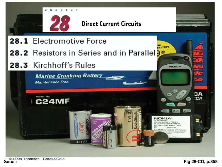
Fig 28-CO, p.858. A constant current can be maintained in a closed circuit through the use of a source of emf, (such as a battery or generator) that produces an electric field and thus may cause charges to move around a circuit.

E N D
A constant current can be maintained in a closed circuit through the use of a source of emf, (such as a battery or generator) that produces an electric field and thus may cause charges to move around a circuit. One can think of a source of emf as a “charge pump.” When an electric potential difference exists between two points, the source moves charges “uphill” from the lower potential to the higher. The emf describes the work done per unit charge, and hence the SI unit of emf is the volt.
assume that the connecting wires have no resistance. • The positive terminal of the battery is at a higher potential than the negative terminal. If we neglect the internal resistance of the battery, the potential difference across it (called the terminal voltage) equals its emf. • However, because a real battery always has some internal resistance r, the terminal voltage is not equal to the emf for a battery in a circuit in which there is a current. A circuit consisting of a resistor connected to the terminals of a battery.
As we pass from the negative terminal to the positive terminal, the potential increases by an amount ε. • As we move through the resistance r, the potential decreases by an amount Ir, where I is the current in the circuit. • ε : is equivalent to the open-circuit voltage—that is, the terminal voltage when the current is zero. The emf is the voltage labeled on a battery,…. • the terminal voltage V must equal the potential difference across the external resistance R, often called the load resistance.
The resistor represents a load on the battery because the battery must supply energy to operate the device. The potential difference across the load resistance is ΔV = IR the changes in electric potential as the circuit is traversed in the clockwise direction • the total power output Iεof the battery is delivered to the external load resistance in the amount I 2R and to the internal resistance in the amount I 2r. Fig 28-2b, p.860
* A battery has an emf of 15.0 V. The terminal voltage of the battery is 11.6 V when it is delivering 20.0 W of power to an external load resistor R. (a) What is the value of R? (b) What is the internal resistance of the battery?
When two or more resistors are connected together as are the light- bulbs, they are said to be in series. In a series connection, all the charges moving through one resistor must also pass through the second resistor. This relationship indicates that the equivalent resistance of a series connection of resistors is always greater than any individual resistance.
Now consider two resistors connected in parallel, When the current I reaches point a in Figure 28.5b, called a junction, it splits into two parts, with I1 going through R1 and I 2 going through R2 . A junction is any point in a circuit where a current can split
…the equivalent resistance of two or more resistors connected in parallel is always less than the least resistance in the group. * Household circuits are always wired such that the appliances are connected in parallel. Each device operates independently of the others so that if one is switched off, the others remain on. In addition, the devices operate on the same voltage.
(a) Find the equivalent resistance between points a and c. (b) What is the current in each resistor if a potential difference of 42V is maintained between a and c ?
Three resistors are connected in parallel as shown in Figure 28.7. A potential difference of 18 V is maintained between points a and b. (a) Find the current in each resistor. (b) Calculate the power delivered to each resistor and the total power delivered to the combination of resistors.
(c) Calculate the equivalent resistance of the circuit. Exercise :Use Req to calculate the total power delivered by the battery. Answer :200 W.
- we can analyze simple circuits using the expression V IR and the rules for series and parallel combinations of resistors. Very often, however, it is not possible to reduce a circuit to a single loop. - The procedure for analyzing more complex circuits is greatly simplified if we use two principles called Kirchhoff’s rules:
Kirchhoff’s first rule is a statement of conservation of electric charge. the charge passes through some circuit elements must equal the sum of the decreases in energy as it passes through other elements. The potential energy decreases whenever the charge moves through a potential drop IR across a resis-tor or whenever it moves in the reverse direction through a source of emf. The potential energy increases whenever the charge passes through a battery from the negative terminal to the positive terminal. Fig 28-14, p.870
Kirchhoff’s second rule follows from the law of conservation of energy. Sum Let us imagine moving a charge around the loop. When the charge returns to the starting point, the charge–circuit system must have the same energy as when the charge started from it. The sum of the increases in energy in some circuit elements must equal the sum of the decreases in energy in other elements. The potential energy decreases whenever the charge moves through a potential drop IR across a resistor or whenever it moves in the reverse direction through a source of emf. The potential energy increases when-ever the charge passes through a battery from the negative terminal to the positive terminal.
You should note the following sign conventions when using the second rule: • Because charges move from the high-potential end of a resistor to the low potential end, if a resistor is traversed in the direction of the current, the change in potential V across the resistor is - IR • If a resistor is traversed in the direction opposite the current, the change in potential V across the resistor is + IR • If a source of emf (assumed to have zero internal resistance) is traversed in the direction of the emf (from - to+ ), the change in potential V is +ε. The emf of the battery increases the electric potential as we move through it in this direction. • If a source of emf (assumed to have zero internal resistance) is traversed in the direction opposite the emf (from + to - ), the change in potential V is - ε. In this case the emf of the battery reduces the electric potential as we move through it. Each circuit element is traversed from left to right
(a) Find the current in the circuit. (Neglect the internal resistances of the batteries.) Traversing the circuit in the clockwise direction, starting at a, we see that a →b represents a potential change of +ε1 , b → c represents a potential change of - IR1 , c → d represents a potential change of -ε2 , and d → a represents a potential change of -IR2 . Applying Kirchhoff’s loop rule gives Fig 28-16, p.871
(b) What power is delivered to each resistor? What power is delivered by the 12-V battery? The 12-V battery delivers power Iε2. Half of this power is delivered to the two resistors, as we just calculated. The other half is delivered to the 6-V battery, which is being charged by the 12-V battery.
Find the currents I1 , I2 , and I3 in the circuit We arbitrarily choose the directions of the currents as labeled in Figure Substituting Equation (1) into Equation (2) gives Dividing each term in Equation (3) by 2 and rearranging gives Subtracting Equation (5) from Equation (4) eliminates I 2 , giving The fact that I 2 and I 3 are both negative indicates only that the currents are opposite the direction we chose for them. However, the numerical values are correct.
Exercise Find the potential difference between points b and c . Answer 2 V.
Q3:(a) find the current in each resistor in Figure below. (b) Find the potential difference between points c and f. Which point is at the higher potential?