Download
1 / 4
40 likes | 190 Views
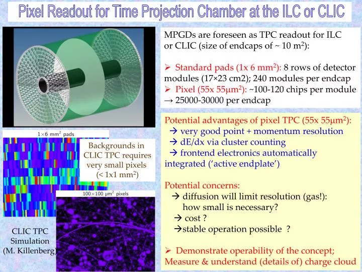
Pixel Readout for Time Projection Chamber at the ILC or CLIC. MPGDs are foreseen as TPC readout for ILC or CLIC (size of endcaps of ~ 10 m 2 ): Standard pads (1x 6 mm 2 ): 8 rows of detector m odules (17×23 cm2); 240 modules per endcap Pixel (55x 55 m m 2 ): ~100-120 chips per module

E N D
Pixel Readout for Time Projection Chamber at the ILC or CLIC • MPGDs are foreseen as TPC readout for ILC • or CLIC (size of endcaps of ~ 10 m2): • Standard pads (1x 6 mm2): 8 rows of detector • modules (17×23 cm2); 240 modules per endcap • Pixel (55x 55mm2): ~100-120 chips per module • → 25000-30000 per endcap • Potential advantages of pixel TPC (55x 55mm2): • very good point + momentum resolution • dE/dx via cluster counting • frontend electronics automatically integrated (‘active endplate’) • Potential concerns: • diffusion will limit resolution (gas!): • how small is necessary? • cost ? • stable operation possible ? • Demonstrate operability of the concept; • Measure & understand (details of) charge cloud Backgrounds in CLIC TPC requires very small pixels (< 1x1 mm2) CLIC TPC Simulation (M. Killenberg)
Going to Larger Areas: “Octopuce” Modules based on the 2 x 4 Timepix ASICs Saclay InGrid 3 GEM Bonn “Octopuce” / InGrid • 2010: Saclay / NIKHEF “Octopuce” (InGrid): studies with X-Rays and at DESY e- beam • 2012-2013 : 2 Saclay / NIKHEF “Octopuce”(InGrid): 1 - some issues with readout; 2 - OK • 2013: 2 Bonn “Octoboards” (InGrid & 3-GEM): studies with RD51 SRS at DESY e- beam Single point resolution vs drift distance (Octopuce / InGrid): Image from Bonn/“Octoboard” (5 GeV e-): InGrid: each electron avalanche corresponds to single pixel hit 4 Timepix ASICs Bonn/ InGrid Bonn/ InGrid
Saclay “Octopuce’s”: Study of Uniformity with X-Rays & Cosmics Cosmics DATA: Octopuce 3 Uniform irradiation with X-Rays DATA: Octopuce 1 Simulation (Kyiv Univ.) • Single electron sensitivity ~ 100 % (in the central areas of the chips) • Work is ongoing to better understand & improve field distortions in-between and at the borders of “InGrid’s (based on simulation) Electric field configuration RD51-NOTE- 2013-002
Future Plans: Pixel Readout of MPGD - Proof-of-Principle of Si-TPC Mid-term plan (3 years): Develop and equip a full LCTPC module (~100 chips) with “InGrid”s, using “Octopuce” module as the basic building block Pixel LC-TPC Consortium: Bonn, Saclay, NIKHEF, DESY, LAL, Kyiv University • Improved mass production of “InGrid”s(lessdead area, higheryield, protection) • Minimizefielddistortionsin the « Octopuce » plane; work on more realisiticcooling and power pulsing • Develop simulation chain to compare momentumresolution, double trackresolution, dE/dx and pattern recognition to pad-basedreadoutand to optimize the geometry • Experimental dE/dx study by cluster counting using InGridat the LAL/PHIL facility